 by
by In this tutorial, we explain the wiring diagram for the differential wheeled robot (ver 1.0). In the previous tutorial whose link is given here, we explained how to write ROS and Arduino nodes for remotely controlling the robot and for remotely reading encoder pulses. The YouTube tutorials explaining the wiring diagram and remote control are given below.
Wiring of the Bluetooth HC-06 Module and Important Comments About Uploading the Sketch
The wiring diagram for the HC-06 Bluetooth module is given below.
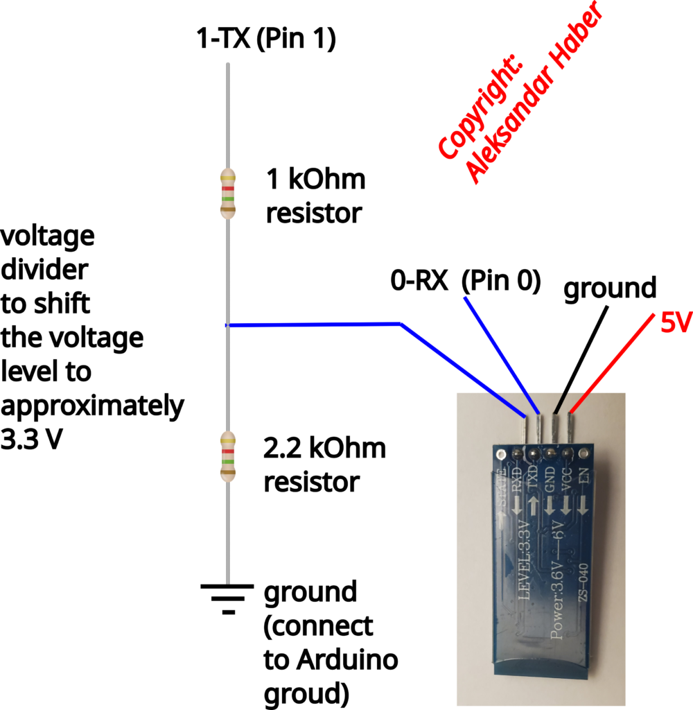
The voltage divider circuit is used to set the input voltage to pin RXD to approximately 3.3 V. This is done since the pin coming from Arduino is at the 5 V level. Then, the TXD pin of HC-06 should be connected to the 0-RX pin of Arduino Mega. This is actually the pin 0 of Arduino Mega. On the other hand, the pin RXD of HC-06 should be indirectly connected via the voltage divider to the 1-TX pin of Arduino Mega. This is actually pin 1 of Arduino Mega. The ground should be connected to Arduino ground and 5V should come from Arduino 5V pin. Note over here the following:
- We do not need to use BTSerial library to read information from HC-06 in Arduino. The communication is handled by the Arduino Rosserial Library indirectly. However, for this type of connection to work, the RXD and TXD pins of HC-06 need to be connected to the 1-TXD and 0-RX pins of Arduino Mega. This is because these two pins are standard pins for handling serial communication.
- Also, when uploading the Arduino sketch and code from your computer, you need to disconnect pins 1-TXD and 0-RX. That is you need to disconnect communication pins of HC-06. If you do not do that you will not be able to upload the sketch by using USB serial connection. This is because is something is connected to 1-TXD and 0-RX, then the serial USB connection cannot be established.
- Before running the HC-06 module it is a good practice to verify the baud rate. In my video tutorial, I used 9600 baud rate. Consequently, verify that HC-06 is running with this baud rate. You can do that by following this tutorial and by using the AT commands.
Encoder Wiring
We have two encoders that detect motor wheel rotation. We are using low-cost encoders with the product number LM393. The wiring sketch for both encoders is given below.
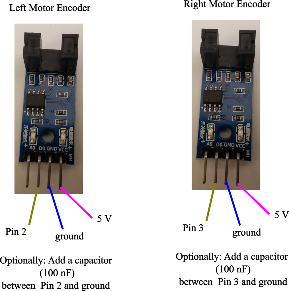
The left encoder should be connected to pin 2 or Arduino Mega and the right encoder should be connected to the pin 3 of Arduino Mega. You need to attach the encoders to the interrupt pins of Arduino Maga. The interrupt pins are 2 and 3. The ground should be the Arduino ground pin and 5V should be connected to the 5V Arduino pin. More details about these encoders are given in our previous tutorial which can be found here.