 by
by
In this mechatronics and Internet of Things (IoT) tutorial, we will learn how to
- Properly connect the Bluetooth Wireless adapter/module HC-06 with Arduino.
- Control Arduino from a mobile (cell) phone by using the Bluetooth module HC-06.
By learning how to establish wireless communication between Arduino and external devices you can start creating amazing Internet of Things projects that will integrate remote control, robotics, artificial intelligence, robot autonomy, etc.
The basic wiring diagram for the HC-06 module is shown below.
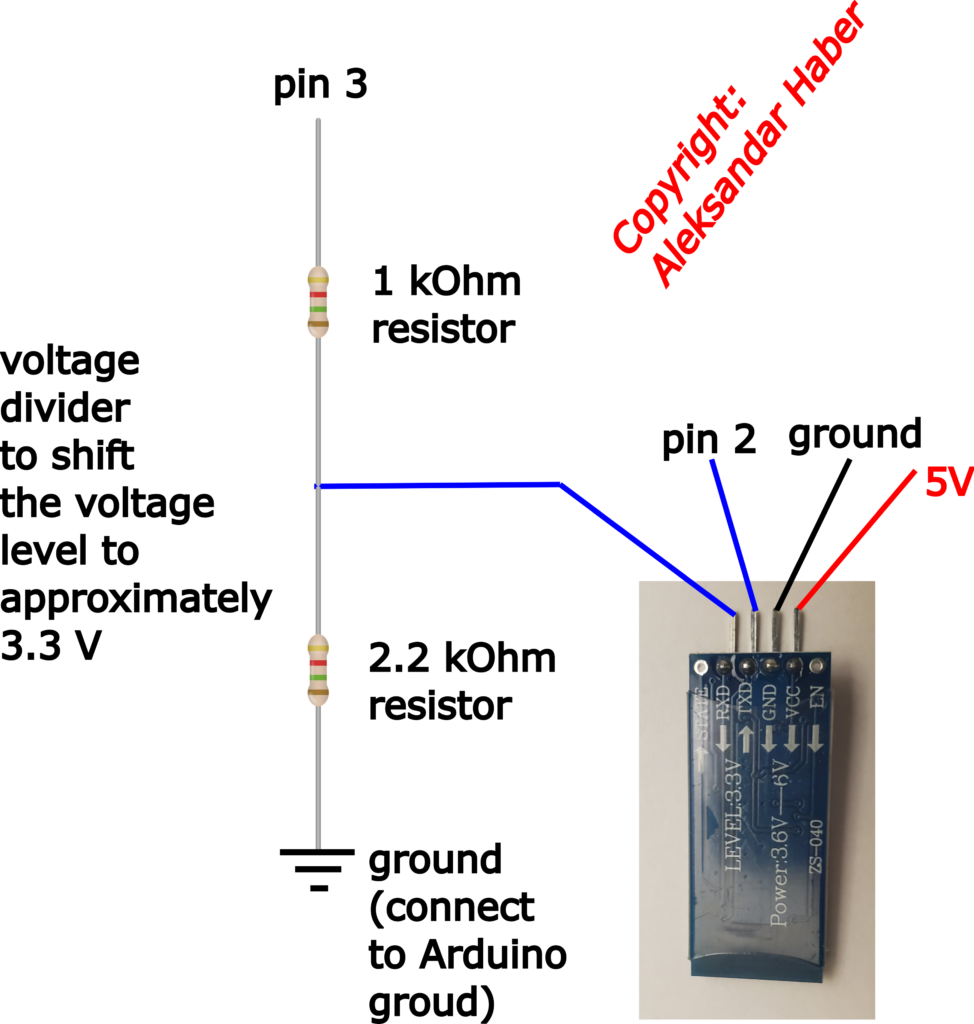
There are 4 pins of HC-06 that need to be connected to Arduino. In our case, we are using Arduino Uno, however, everything explained in this tutorial can be applied to other Arduino versions.
- The pin VCC should be connected to 5V pin of Arduino.
- The pin GND should be connected to the ground pin of Arduino.
- The pin TXD should be connected to the digital pin number 2 of Arduino. In my code, I selected the pin number 2, however, you can also select any other pin number in the range 2-13 (do not use pins 0 and 1). Also, do not connect TXD to the analog pins!
- The pin RXD should be connected to the digital pin number 3 of Arduino through the voltage divider (see the comments above). That is, we connect pin 3 of Arduino to the input of the voltage divider, and the output of the voltage divider circuit shown above. The purpose of the voltage divider is to shift the Arduino pin 3 voltage from 5 V to approximately 3.3-volt level necessary for the pin RXD of the HC-06. In our case, we are using the
 and
and  resistors, and consequently, the voltage level of the pin RXD is
 (1)

That is close enough to 3.3 volts.
After, you wired the circuit, enter this Arduino code in order to test the communication:
#include <SoftwareSerial.h>
unsigned int Tx=2;
unsigned int Rx=3;
SoftwareSerial BTserial(Tx, Rx);
// HC-06 TX Port should be connected to the digital pin Tx=2 of Arduino
// HC-06 RX Port should be connected to the digital pin Rx=3 of Arduino (through a voltage divider)

void setup()
{
    Serial.begin(9600);

    BTserial.begin(9600);
}

void loop()
{
    // Read the response from the HC-06 and send it to the Arduino Serial Monitor
    if (BTserial.available())
    {
        Serial.write(BTserial.read());
    }

    // Read the input message from the Arduino Serial Monitor and send it to HC-06
    if (Serial.available())
    {
        BTserial.write(Serial.read());
    }

}
To establish communication with the HC-06, we are using the Software Serial library and its header file “SoftwareSerial.h”. Then, we set the baud rate of the Serial Monitor and HC-06 to 9600. HC-06 baud rate is set by default to 9600, however, you can change this later on. The purpose of this code is to test if we can communicate with HC-06 by sending the messages through the Arduino Serial port and monitor, reading the response of HC-06, and plotting the response on our Arduino Serial monitor. With the piece of code
    if (Serial.available())
    {
        BTserial.write(Serial.read());
    }
We can read the command we enter manually through the Arduino serial monitor, and we send that message to the HC-06. To do that, we use the function BTserial.write(). This will send the message to our HC-06. Then, HC-06 will interpret this message and send us the reply. The reply is read and printed to our Arduino Serial monitor by using this code:
    if (BTserial.available())
    {
        Serial.write(BTserial.read());
    }
When you upload the code and after you open the serial monitor, make sure that “No line ending” option is selected in right lower bottom of the Arduino Serial monitor (as shown in the figure below).
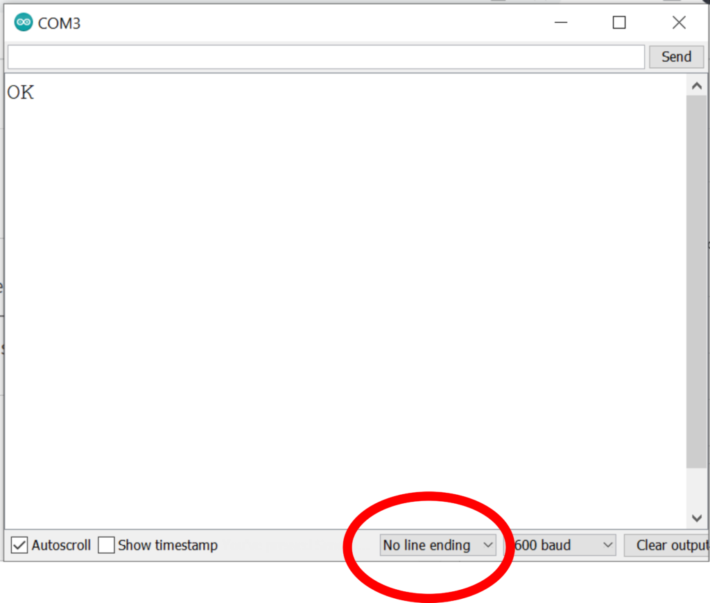
Next, type in the Arduino serial monitor “AT”, and press Enter. The reply from HC-06 should be “OK”. This means that everything is properly set-up. Then, you can also ask AT+VERSION, to get information about the firmware version. In our case, the reply is “linvorV1.8”. Here is the full list of commands that you can enter:
ENTER FROM SERIAL PORT                REPLY FROM HC-06               EXPLANATION
 AT                                                                  OK                                                   Test is communication is working
AT+VERSION                                              OKlinvorV1.8                              Firmware version.
AT+NAMEmoduleName                        OKsetname                                 Changes the module name to “moduleName”
AT+PINpinNumber                                  OKsetPIN                                     Set the Wireless PIN to "pinNumber"
AT+BAUD1                                                   OK1200                                        Changes the baud rate to 1200
AT+BAUD2                                                   OK2400                                        Changes the baud rate to 2400
AT+BAUD3                                                   OK4800                                        Changes the baud rate to  4800
AT+BAUD4                                                   OK9600                                        Changes the baud rate to 9600
AT+BAUD5                                                   OK19200                                      Changes the baud rate to 19200
AT+BAUD6                                                   OK38400                                      Changes the baud rate to 38400
AT+BAUD7                                                   OK57600                                      Changes the baud rate to 57600
AT+BAUD8                                                   OK115200                                   Changes the baud rate to 115200
AT+BAUD9                                                   OK230400                                   Changes the baud rate to 230400
AT+BAUDA                                                   OK460800                                   Changes the baud rate to 460800
AT+BAUDB                                                   OK921600                                   Changes the baud rate to 921600
AT+BAUDC                                                   OK1382400                                 Changes the baud rate to 1382400
ENTER FROM SERIAL PORT REPLY FROM HC-06 EXPLANATION
AT OK Test is communication is working
AT+VERSION OKlinvorV1.8 Firmware version.
AT+NAMEmoduleName OKsetname Changes the module name to “moduleName”
AT+PINpinNumber OKsetPIN Set the Wireless PIN to “pinNumber”
AT+BAUD1 OK1200 Changes the baud rate to 1200
AT+BAUD2 OK2400 Changes the baud rate to 2400
AT+BAUD3 OK4800 Changes the baud rate to 4800
AT+BAUD4 OK9600 Changes the baud rate to 9600
AT+BAUD5 OK19200 Changes the baud rate to 19200
AT+BAUD6 OK38400 Changes the baud rate to 38400
AT+BAUD7 OK57600 Changes the baud rate to 57600
AT+BAUD8 OK115200 Changes the baud rate to 115200
AT+BAUD9 OK230400 Changes the baud rate to 230400
AT+BAUDA OK460800 Changes the baud rate to 460800
AT+BAUDB OK921600 Changes the baud rate to 921600
AT+BAUDC OK1382400 Changes the baud rate to 1382400
For example, you can change the wireless pin number. Note that the default pin number is “1234” or for some models “0000”. You will need the wireless pin number to set-up the communication from your phone to the HC-06 device. For the time being, do not change the pin number, you can do it later on, once you become familiar with the basic functionality of the HC-06 device.
Now, we can proceed further. Our next task is to connect a phone to our Arduino device by using the Bluetooth connection. First, enter this code in Arduino:
#include <SoftwareSerial.h>
unsigned int Tx=2;
unsigned int Rx=3;
SoftwareSerial BTserial(Tx, Rx);
// HC-06 TX Port should be connected to the digital pin Tx=2 of Arduino
// HC-06 RX Port should be connected to the digital pin Rx=3 of Arduino (through a voltage divider)


void setup()
{
    Serial.begin(9600);

    BTserial.begin(9600);
}

String totalMessage="";
String printMessage="";
String sentBackMessage="";
char receivedCharacter;
char endMessageCharacter='#';
void loop()
{

    while (BTserial.available())
    {
        receivedCharacter=(char)BTserial.read();
        totalMessage=totalMessage+receivedCharacter;
        if (receivedCharacter==endMessageCharacter)
        {
          printMessage=totalMessage;
          totalMessage="";
          Serial.print(printMessage);
          sentBackMessage="Arduino sends back "+ printMessage;
          BTserial.print(sentBackMessage);
        }

     }

}
This code will read a message sent by the phone, it will display it on the Arduino Serial Monitor, and it will send the message back. The messages send from the phone should be in this format:
message#
Where “#” is the end of the message character. You can change this end of the message character as you wish in the code. The while loop shown below
 while (BTserial.available())
    {
        receivedCharacter=(char)BTserial.read();
        totalMessage=totalMessage+receivedCharacter;
        if (receivedCharacter==endMessageCharacter)
        {
          printMessage=totalMessage;
          totalMessage="";
          Serial.print(printMessage);
          sentBackMessage="Arduino sends back "+ printMessage;
          BTserial.print(sentBackMessage);
        }

     }
will be activated if “BTserial.available()” returns one. That is, if there is a set of characters in the serial port buffer of the HC-06. Then, these characters will be read one by one, and a string called “totalMessage” will be formed. When the read character is “#”, the message will be printed. We print the string called “printMessage” in our Serial Monitor. Then, we create another string called “sentBackMessage” and we send it back to our phone by using the function “BTserial.print()”. It is simple as that.
IMPORTANT: Once HC-06 is powered-up, you will notice that the led indicator light of this device is blinking. This means that the device is working. However, once you pair this device with your phone or any other device, and ONLY after you establish a communication link (you connect), you will see that the led is continuously on, that is, it is not blinking anymore.
Once you upload this code, you have to do the following:
- Open a Bluetooth connection on your phone and find the HC-06. By default, HC-06 name is “HC06”. Connect to the HC-06 from your phone.
- Then, you will need an app to communicate with HC-06. If you are using Android, go to Google Play and search, download, and install the app called “Serial Bluetooth Terminal”. Then, connect to HC-06 from this app. And start sending messages (for more information, see the video tutorial).