 by
by In this tutorial, we explain:
- How to interface LM393 Encoder with Arduino.
- How to write simple Arduino code for measuring the pulses generated by the encoder.
- How to write Arduino code for measuring the total angle and angular velocity by using the encoder.
The experimental setup is explained in the accompanying video tutorial given below.
The photograph of the complete experimental setup is given below.
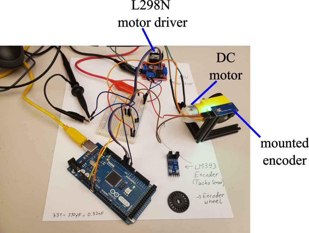
The encoder and the wheel are mounted to the motor by using the MakerBeam aluminum extrusions. The motor is attached to the L298N motor driver. The driver is interfaced with Arduino. A complete tutorial on how to interface this motor driver with the DC motor and with Arduino is given here.
The connection diagram of the encoder is shown below.
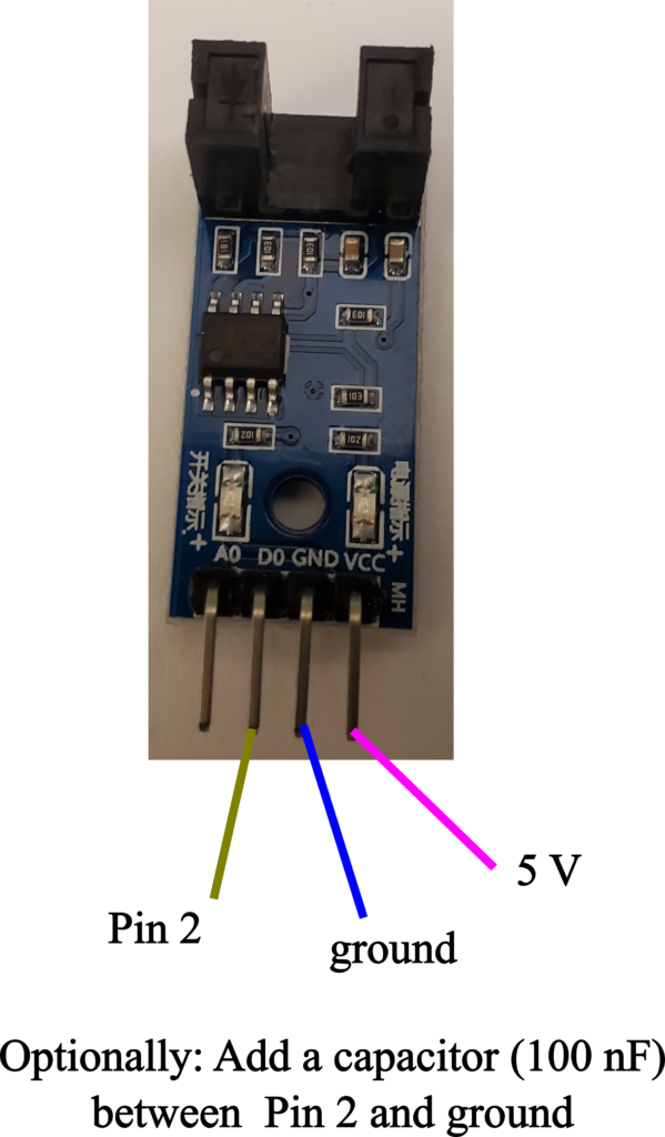
The “DO” pin of the encoder should be attached to the Pin 2 of the Arduino. Another option is to use Pin 3 of Arduino. Pins 2 and 3 of Arduino are interrupt pins, and consequently, the encoder should be attached to one of these two pins. If you attach the encoder to other pins, the encoder might not work properly, or you will have to write extra code to make it work properly. Ground should be attached to the Arduino ground and 5V should be connected to the Arduino 5V pin. To partly stabilize the encoder pulses and to eliminate some noise, you need to add a capacitor between Pin 2 and ground. We were using 100 nF capacitor for that purpose.
The motor wiring diagram is given below.
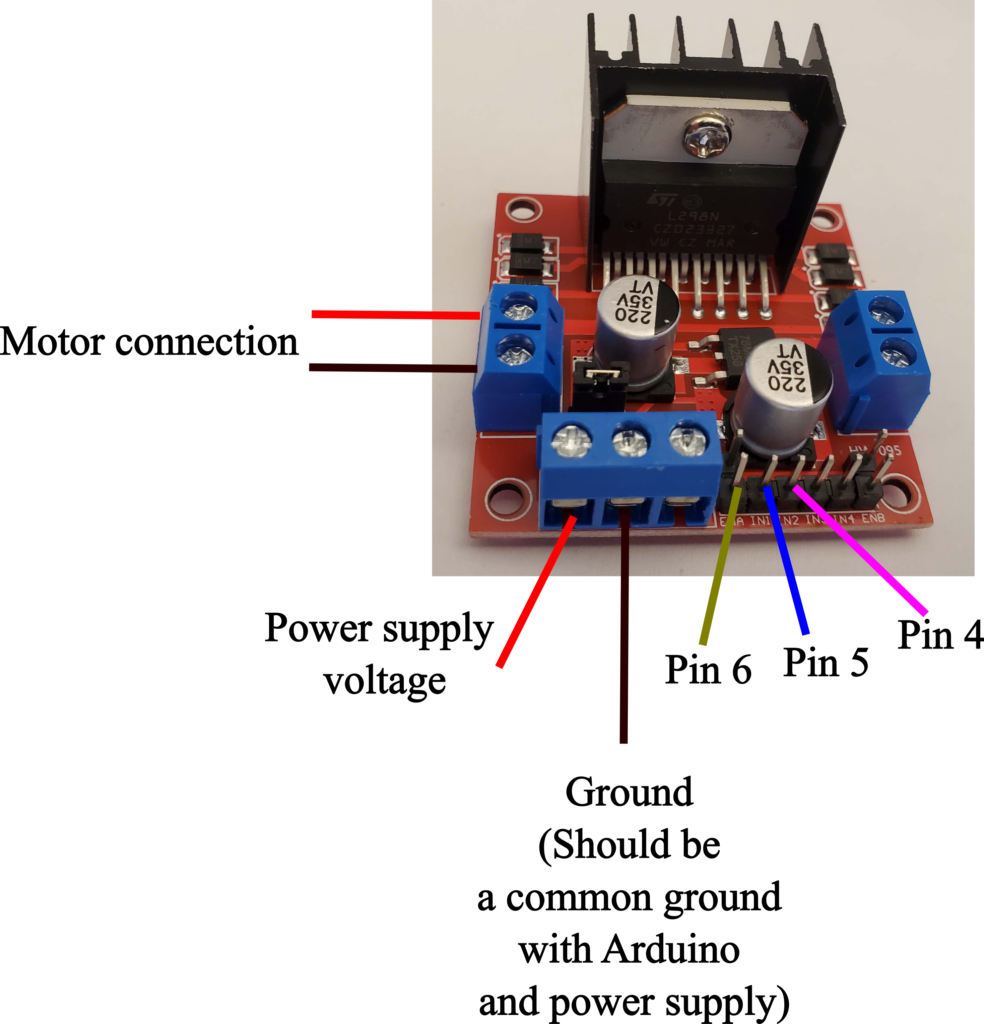
This diagram is self-explanatory. You need to connect the control pins of the motor to Pins 4,5, and 6 of Arduino.
First, we present a simple code for testing the encoder. The code shown below measures and plots the total number of encoder pulses detected by Arduino. The code is explained in the YouTube video.
// encoder pin
int encoderPin=2;
volatile unsigned long totalPulses = 0;

void setup() {

  // set the encoder pin
  pinMode(encoderPin, INPUT);
  // attach the interrupt for tracking the pulses
  // one the pulse is detected, interruptFunction() is called
  attachInterrupt(digitalPinToInterrupt(encoderPin), interruptFunction, RISING);

  Serial.begin(9600);

}

void loop() {

}

void interruptFunction(){
         // increment the total number of pulses
        totalPulses = totalPulses + 1;
        Serial.println(totalPulses);

}
The variable “totalPulses” is used to store the total pulses. The encoder is attached as an interrupt by using
attachInterrupt(digitalPinToInterrupt(encoderPin), interruptFunction, RISING);
The second argument of this function is the name of the function that is called once the pulse is detected. The name of this function is “interruptFunction”. This function will simply count the pulses and display them on the screen through the Serial monitor.
The next Arduino code explains how to measure the motor angular velocity and total angle of rotation. The detailed explanation of this code is given in the YouTube tutorial at the top of this page.
// encoder pin
int encoderPin=2;
// motor pins
int ENA = 6;
int IN1 = 5;
int IN2 = 4;

// we have 20 holes, and consequently, angle/pulse=360/20= 18 degrees per pulse
volatile int anglePerPulse=18;
// total pulses from the start of the Arduino program
volatile unsigned long totalPulses = 0;
// total angle calculated from totalPulses
volatile long totalAngle=0;
// variables for measuring time
volatile unsigned long lastTime=0;
volatile unsigned long currentTime=0;
volatile double deltaT=0; // deltaT=currentTime-lastTime


// this is the average angular velocity that we compute on
// the basis of the variables shown below
volatile double angularVelocity=0;
// total time until sumPulses reaches averageSample
volatile unsigned long timeAverageAngularVelocity=0;
// sumPulses goes from 0 to averageSample, and then it is set back to zero
volatile int sumPulses=0;
// how many pulses we will take to calculate the average angular velocity
volatile int averageSample=50;

void setup() {
  // set the motor pins
  pinMode(ENA, OUTPUT);
  pinMode(IN1, OUTPUT);
  pinMode(IN2, OUTPUT);

  // set the encoder pin
  pinMode(encoderPin, INPUT);
  // attach the interrupt for tracking the pulses
  // one the pulse is detected, interruptFunction() is called
  attachInterrupt(digitalPinToInterrupt(encoderPin), interruptFunction, RISING);

  Serial.begin(9600);
  // obtain the current time
  lastTime=millis();
}

void loop() {
  // set the motor speed
  analogWrite(ENA, 150);
  // direction
  digitalWrite(IN1,HIGH);
  digitalWrite(IN2, LOW);
}

void interruptFunction(){
        // get the current time
        currentTime=millis();
        // deltaT is approximately equal to the time between the pulses
        // there is a delay...
        deltaT=currentTime-lastTime;
        lastTime=currentTime;

        // increment the total number of pulses
        totalPulses = totalPulses + 1;
        // calculate the total angle
        totalAngle= totalPulses*anglePerPulse;

        // this is another sum of pulses that is used to calculate
        // the average angular velocity
        // this sum is set to zero after averageSample
        sumPulses=sumPulses+1;
        // track the total time between computing the averages
        timeAverageAngularVelocity=timeAverageAngularVelocity+deltaT;

       // here we calculate the average angular velocity
       // after averageSample pulses
       if (sumPulses>=averageSample)
       {
          angularVelocity=1000*((double)(sumPulses * anglePerPulse) )/((double) timeAverageAngularVelocity );
          Serial.println((String)"Total angle:"+totalAngle+" Angular velocity:"+angularVelocity);
          sumPulses=0;
          timeAverageAngularVelocity=0;
       }


}