 by
by In this robotics and mechatronics tutorial, we explain
1.) How to control DC motors by using Arduino and L298N motor driver.
2.) How to connect the L298N driver to a DC motor and Arduino.
3.) How to write an Arduino code for controlling a DC motor
The YouTube tutorial is given below.
Connect L298N Motor Driver to Motor and Arduino
The photo of the driver with all the connections is given below.
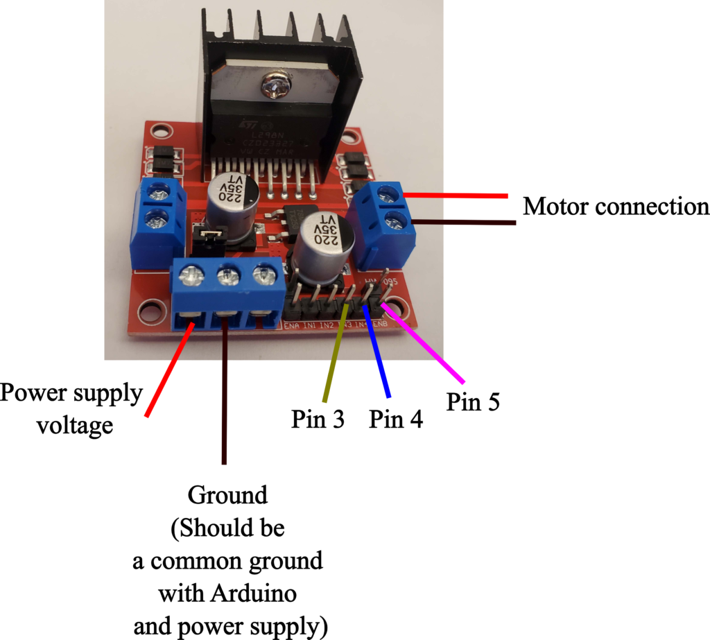
In this tutorial, we control the right motor. Consequently, the motor should be connected to the right connection pins of the motor driver. On the other hand, the motor driver L298N can be used to control two motors at the same time. Another motor can be connected to the left connection pins (opposite from the connections we are currently using).
We connect the power supply voltage and its ground to the pins in the lower left corner. In our case, we are using an external power supply. However, you can also connect a battery pack to these connections. Also, it should be emphasized that the Arduino ground and power supply ground should be connected together and then connected to the L298N driver. We provide 12 [V] to the motor. In your case, you will have to change this supply voltage depending on the type of motor being used. Next, we need to connect the Arduino pins. We have the following connections:
- IN3 port of the driver should be connected to Pin 3 of Arduino. This digital pin together with IN4 is used to control the direction of the motor. We will explain how to control the direction later on in this tutorial.
- IN4 port of the driver should be connected to Pin 4 of Arduino. This digital pin together with IN3 (see above) is used to control the direction of the motor. We will explain how to control the direction later on in this tutorial.
- ENB port of the driver should be connected to Pin 5 of Arduino. This pin is used to control the speed of the motor. This is explained later on in the tutorial.
We control the motor direction like this:
- Motor OFF: IN3-LOW and IN4-LOW (apply a low voltage to IN3 and IN4)
- Motor OFF: IN3-HIGH and IN4-HIGH (apply a high voltage to IN3 and IN4)
- Motor ON and forward: IN3-HIGH and IN3-LOW (apply a high voltage to IN3 and low voltage to IN4)
- Motor ON and backward: IN3-LOW and IN3-HIGH (apply a high voltage to IN3 and low voltage to IN4)
We control the motor speed like this:
By using the Arduino function “analogWrite(ENBpinNumber, speed)” we control the motor speed. the ENBpinNumber is the Arduino pin connected to ENB. The “speed” is the speed value in the range from 0 to 255. 0 corresponds to the lowest speed and 255 corresponds to the largest speed. This function writes an analog signal (PWM signal) to the motor pin.
Arduino Code for Controlling DC Motor by Using L298N
The Arduino code for controlling the motor is given below.
// the motor is attached to the right connections of the driver

int IN3 = 3;
int IN4 = 4;
int ENB = 5;


void setup() {
  pinMode(IN3, OUTPUT);
  pinMode(IN4, OUTPUT);
  pinMode(ENB, OUTPUT);

  // turn OFF all the motors

  digitalWrite(IN3, LOW);
  digitalWrite(IN4, LOW);
}

void loop() {
  // Set the speed of the motor (PWM signals) from 0 to 255
  analogWrite(ENB, 220);

  // Set the direction and turn ON
  digitalWrite(IN3, HIGH);
  digitalWrite(IN4, LOW);

  delay(5000);

  // Set the opposite direction and turn ON
  digitalWrite(IN3, LOW);
  digitalWrite(IN4, HIGH);

  delay(5000);

}
First, we define the pins. Then, in the setup function, we set the motor OFF. Then, in the loop function, with the statement
analogWrite(ENB, 220)
We set the speed to 220 value (the maximum value is 255). Then for 5 seconds, we move the motor in one direction by using
digitalWrite(IN3, HIGH);
digitalWrite(IN4, LOW);
Then, for the next five seconds, we move the motor in the opposite direction by using
digitalWrite(IN3, LOW);
digitalWrite(IN4, HIGH);
And that is it, this a minimal code that explains how to control the motor.