 by
by In this tutorial, we will learn how to create a URDF file and model of a four-wheeled mobile robot in Robot Operating System (ROS). We explain how to model the robot by using ROS Noetic distribution. In particular, we will learn how to
- Define robot geometry together with links and joints in the Unified Robotics Description Format (URDF) file.
- Create a lunch file for visualizing the robot geometry.
- Visualize the robot geometry in RViz ROS simulation environment.
But before we start with explanations we have to explain the main motivation for creating this video tutorial. Namely, online and on YouTube you can find a number of tutorials on how to model robots in ROS. However, to the best of our knowledge, these tutorials are either incomplete or obsolete. That is, they are not applicable to the current ROS Noetic distribution. In this tutorial, we explain how to model the robot’s geometry in ROS Noetic distribution.
In this tutorial, for clarity and brevity of presentation, we consider a relatively simple robot geometry. However, everything explained in this video tutorial can be generalized to much more complex 3D robot geometries and CAD models. The YouTube tutorial accompanying this webpage tutorial is given below.
Four-Wheeled Robot Robot Geometry
The final robot model is visualized below by using Rviz.
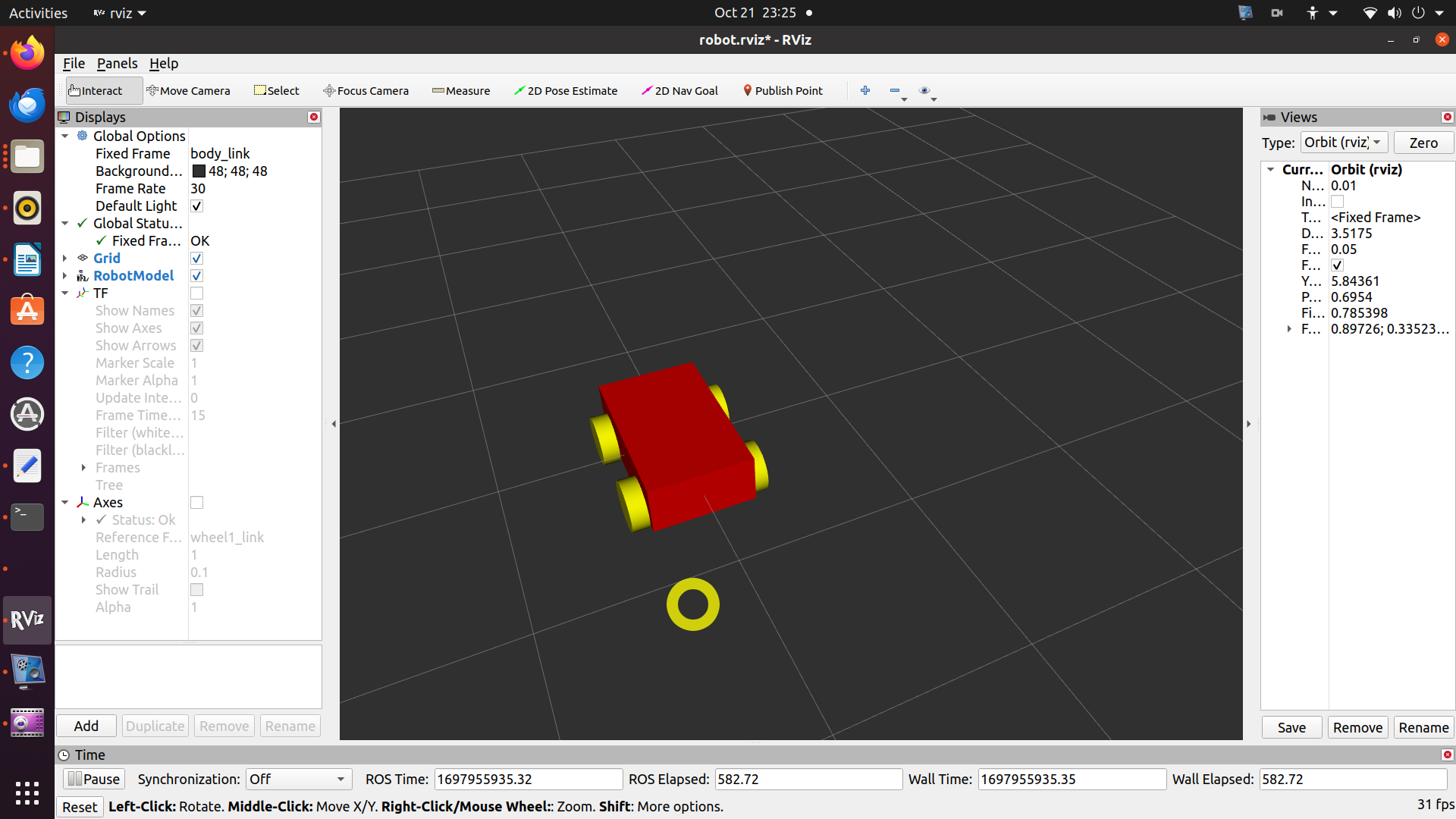
It consists of a robot base and 4 wheels. The base and wheels are called links in the ROS terminology. Between the robot base and wheels, we have 4 joints that enable wheel rotation. That is, in a ROS URDF file, the robot geometry consists of links and joints. The figure below shows the top view of the robot geometry.

This top view defines almost all geometrical parameters, except the z-axis locations of the centers of the wheels and the $z$-axis height of the robot body. The centers of the wheels are at $z=-0.1$. The $z$-axis robot height is $0.3$. That is, the center of the body is at $(0,0,0)$, the bottom surface is at $z=-0.15$, and the top surface is $z=0.15$.
STEP 1: Install the necessary packages
We assume that the ROS Noetic distribution is installed. First, we need to install RViz. RViz is a ROS visualization software. We do that by opening a Linux terminal and typing
sudo apt-get install ros-noetic-rviz
Then, to test the installation, open a new terminal and start Roscore. Roscore is a program that we always need to run when running a ROS program or a package. We do that by typing
roscore
Next, in the original terminal, we open RViz software by typing
rosrun rviz rviz
Next, we install the URDF modeling package
sudo apt-get install ros-noetic-urdf
STEP 2: CREATE THE WORKSPACE AND CATKIN PACKAGE
Open a new terminal in order to start the process from scratch. First, we create a workspace folder, run “catkin_make”, and source the workspace
mkdir -p ~/robot_dd/src

cd ~/robot_dd

catkin_make

source ~/robot_dd/devel/setup.bash
Next, we change the working folder, and create the packages
cd ~/robot_dd/src

catkin_create_pkg robot_dd_model_pkg roscpp tf2 geometry_msgs urdf rviz joint_state_publisher_gui
To create the package, we use the ROS command “catkin_create_pkg”. The name of the package that we will create is “robot_dd_model_pkg”. You can modify this name if you want. The last 6 arguments are ROS package dependencies. They are
- roscpp – C++ support for ROS packages
- tf2 – Lets the user keep track of multiple coordinate frames over time.
- geometry_msgs – ROS messages for common geometric primitives such as points, vectors, and poses.
- urdf – C++ parser for URDF package
- rviz – RVIZ package
- joint_state_publisher_gui – contains a GUI tool for setting and publishing joint state values for a given URDF.
STEP 3: CREATE THE URDF FILE AND LAUNCH FILE
First, we create the URDF file of the robot. The abbreviation URDF means Unified Robotics Description Format. This is a file format that contains the description of our robot. To create this file, we first create a folder and move to the created folder.
cd ~/robot_dd/src/robot_dd_model_pkg/
mkdir urdf
cd urdf
Then, in the folder “~/robot_dd/src/robot_dd_model_pkg/”, we create the urdf file by using the “gedit”
gedit robot.urdf
The file is given below. The explanation of the file is given after the code.
<?xml version="1.0"?>
<!-- http://wiki.ros.org/urdf/XML/link  -->
<robot name="differential_drive_robot">

	<!-- This is the body of the robot -->
	<link name="body_link">
		<visual>
			<origin rpy="0 0 0" xyz="0 0 0"/>
			<geometry>
				<box size="1 0.6 0.3" />
			</geometry>

			<material name="red">
				<color rgba="1 0 0 1"/>
			</material>

		</visual>
	</link>


	<!-- This is the back right wheel of the robot -->
	<joint name="wheel1_joint" type="continuous" >
		<parent link="body_link"/>
		<child  link="wheel1_link" />
		<origin xyz="-0.3 -0.35 -0.1" rpy="0 0 0" />
		<axis xyz="0 1 0"/>
	</joint>
	<link name="wheel1_link">
		<visual>
			<origin rpy="1.570795 0 0" xyz="0 0 0"/>
			<geometry>
				<cylinder length="0.1" radius="0.15"/>
			</geometry>

			<material name="yellow">
				<color rgba="1 1 0 1"/>
			</material>
		</visual>
	</link>


	<!-- This is the back left wheel of the robot -->
	<joint name="wheel2_joint" type="continuous" >
		<parent link="body_link"/>
		<child  link="wheel2_link" />
		<origin xyz="-0.3 0.35 -0.1" rpy="0 0 0" />
		<axis xyz="0 1 0"/>
	</joint>
	<link name="wheel2_link">
		<visual>
			<origin rpy="1.570795 0 0" xyz="0 0 0"/>
			<geometry>
				<cylinder length="0.1" radius="0.15"/>
			</geometry>

			<material name="yellow">
				<color rgba="1 1 0 1"/>
			</material>
		</visual>
	</link>


	<!-- This is the front right wheel of the robot -->
	<joint name="wheel3_joint" type="continuous" >
		<parent link="body_link"/>
		<child  link="wheel3_link" />
		<origin xyz="0.3 -0.35 -0.1" rpy="0 0 0" />
		<axis xyz="0 1 0"/>
	</joint>
	<link name="wheel3_link">
		<visual>
			<origin rpy="1.570795 0 0" xyz="0 0 0"/>
			<geometry>
				<cylinder length="0.1" radius="0.15"/>
			</geometry>

			<material name="yellow">
				<color rgba="1 1 0 1"/>
			</material>
		</visual>
	</link>


	<!-- This is the front left wheel of the robot -->
	<joint name="wheel4_joint" type="continuous" >
		<parent link="body_link"/>
		<child  link="wheel4_link" />
		<origin xyz="0.3 0.35 -0.1" rpy="0 0 0" />
		<axis xyz="0 1 0"/>
	</joint>
	<link name="wheel4_link">
		<visual>
			<origin rpy="1.570795 0 0" xyz="0 0 0"/>
			<geometry>
				<cylinder length="0.1" radius="0.15"/>
			</geometry>

			<material name="yellow">
				<color rgba="1 1 0 1"/>
			</material>
		</visual>
	</link>

</robot>
The robot description is given in the environment
<robot name="differential_drive_robot">
...
</robot>
Here, we specify the robot description. For comments, we use the following notation
<!-- This is a comment -->
Then, the robot body, wheels, and links are called “links” by using the ROS and URDF terminology. The body of the robot is described as follows
<!-- This is the body of the robot -->
	<link name="body_link">
		<visual>
			<origin rpy="0 0 0" xyz="0 0 0"/>
			<geometry>
				<box size="1 0.6 0.3" />
			</geometry>

			<material name="red">
				<color rgba="1 0 0 1"/>
			</material>

		</visual>
	</link>
The “link” URDF environment is used to define the robot body. The name of the link is “body_link” and this is the reference that we will use later on in the code to refer to the body of the robot. The “visual” environment is used to define the visual representation of the link. Then, the “origin” environment is used to specify the location and orientation of the coordinate system attached to the center of the mass of the link with respect to the first reference frame that is fixed. Here for clarity, we repeat the Fig. 2 from the top of this webpage:
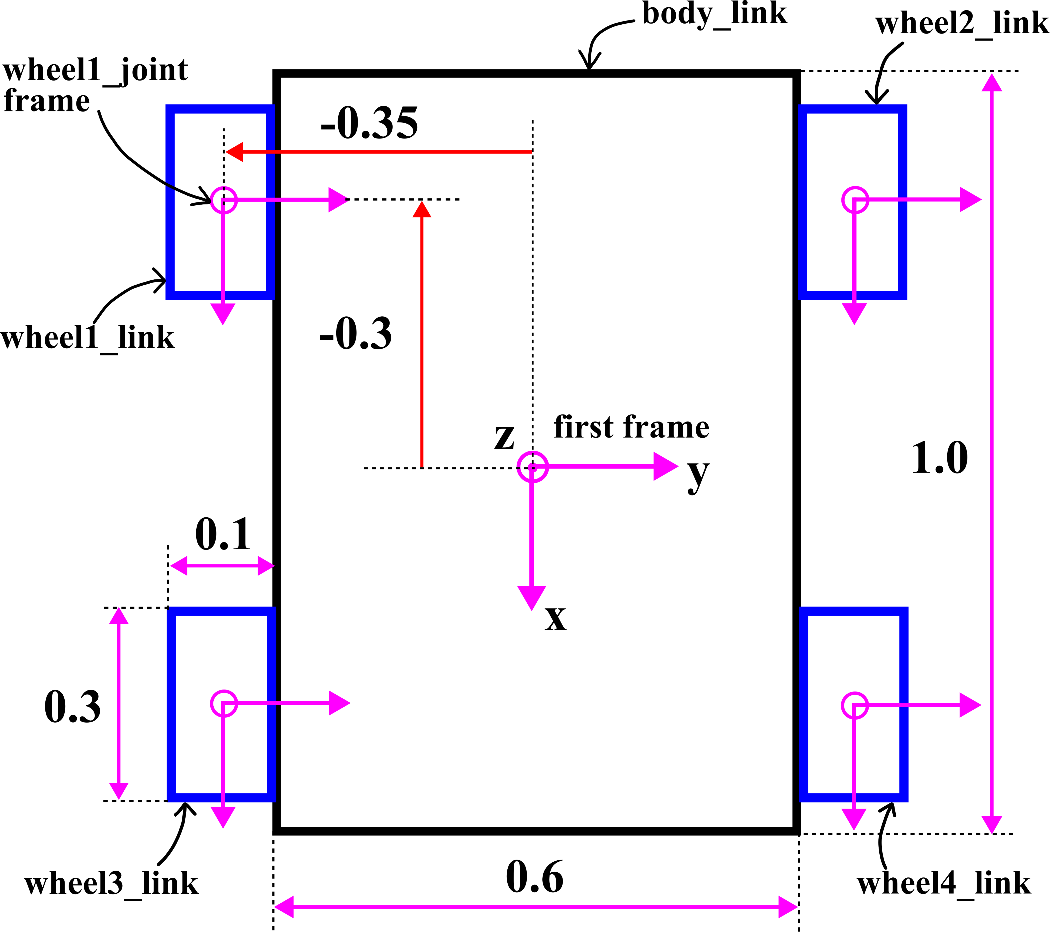
In the origin environment, the “rpy” stands for the roll, pitch, and yaw. These are the Euler angles that specify the orientation of the coordinate system. The notation “xyz” represent the translation of the coordinate system along x, y, and z axes with respect to the fixed frame. In the geometry environment, we specify the geometry of the robot. It is a box, with the dimensions shown in the above figure. Finally, we specify the color of the link.
The code shown below will model the back right wheel of the robot
<!-- This is the back right wheel of the robot -->
	<joint name="wheel1_joint" type="continuous" >
		<parent link="body_link"/>
		<child  link="wheel1_link" />
		<origin xyz="-0.3 -0.35 -0.1" rpy="0 0 0" />
		<axis xyz="0 1 0"/>
	</joint>
	<link name="wheel1_link">
		<visual>
			<origin rpy="1.570795 0 0" xyz="0 0 0"/>
			<geometry>
				<cylinder length="0.1" radius="0.15"/>
			</geometry>

			<material name="yellow">
				<color rgba="1 1 0 1"/>
			</material>
		</visual>
	</link>
Since the wheel is rotating with respect to the robot base, between the wheel and the robot base, we need to add a joint. The joint environment starts with the name of the joint “wheel1_joint”. The type is continuous. This means that the wheel can continuously rotate with respect to the robot base. Every joint should have its parent and child links. The parent link in our case is “body_link” and the child link is “wheel1_link”. The link “wheel1_link” is actually our wheel, and it is defined after the joint environment. Then, we define the origin of the joint. The origin of the joint is the location of the coordinate system of the joint with respect to the fixed coordinate system. The “rpy” represent the orientation, and $xyz$ represent the translation. These parameters are taken from the Fig. 3 above. Then, the parameter “axis” defines the axis of rotation. In our case, the rotation is performed with respect to the y-axis of the joint. Next, we define the wheel link. The origin of the coordinate system attached to the center of the mass of the wheel is rotated for “1.570795” radians around the roll axis (this is the x axis). That is, we rotate the cylinder defining the wheel around the x-axis to place the cylinder in the correct position. The wheel is a cylinder with the radius of 0.15 and with the length of 0.1. Finally, we specify the wheel color. In the same manner, we added other 3 wheels to our robot configuration (the complete code is given at the top of this section.)
The next step is to create a launch file such that we can visualize the robot structure in RViz. First, we need to create the corresponding folder:
cd ~/robot_dd/src/robot_dd_model_pkg/
mkdir launch
cd ~/robot_dd/src/robot_dd_model_pkg/launch
Then, create the launch file like this
gedit robot.launch
The launch file is given below.
<?xml version="1.0" ?>
<launch>
	<arg name="model" />
	<param name= "robot_description"
	textfile="$(find robot_dd_model_pkg)/urdf/robot.urdf" />

<node name="joint_state_publisher_gui"
pkg="joint_state_publisher_gui"
type="joint_state_publisher_gui" />


	<node name="robot_state_publisher" pkg="robot_state_publisher" type="robot_state_publisher" />

	<node name="rviz" pkg="rviz" type="rviz"
	args="-d $(find robot_dd_model_pkg)/robot.rviz" required="true"
	/>

</launch>
This launch file will load the robot geometric description from the created URDF file and it will start the necessary nodes together with RViz. For a complete explanation of the launch file, see the YouTube tutorial at the top of this page.
The final step is to make the packages and workspace. We do that by typing
cd ~/robot_dd
catkin_make
STEP 4: TEST THE MODEL IN RVIZ
First, open a new terminal (do not close the original terminal), and run roscore by typing
roscore
Then, in the original terminal type
roslaunch robot_dd_model_pkg robot.launch
This will bring up the RViz. However, nothing will be displayed. To display the robot model, make the following adjustments
– In Displays window (left upper corner), under Global Options, change fixed frame to “body_link”
– In Displays window, click on add and click on RobotModel and click OK – this option will actually show the robot.
– Then, save this configuration. Click on File, Save Config As, and save the file as: “robot.rviz” in the folder
~/robot_ws/src/robot_dd_model_pkg
where “~” is a Linux shortcut for the home folder.