 by
by In this post, we will learn the basics of Fanuc robot motion instructions that are used to program the robot. A general form of the motion instruction line is given below
“MOTION TYPE” @ “POSITION TYPE” “SPEED” “TERMINATION TYPE” “MOTION OPTION”
A typical motion instruction line will look like this:
1:L P[1] 200 mm/sec FINE
Here is the explanation:
- “1:” is the code line number
- L – is the motion type, that corresponds to the linear motion to the destination point P[1]
- P[1] is the position type, in this case, this is the destination point or position.
- 200 mm/sec is the speed
- FINE is the termination type
- Here we do not have a motion option
1. MOTION TYPE
This instruction describes how the robot moves to a destination position. There are three options:
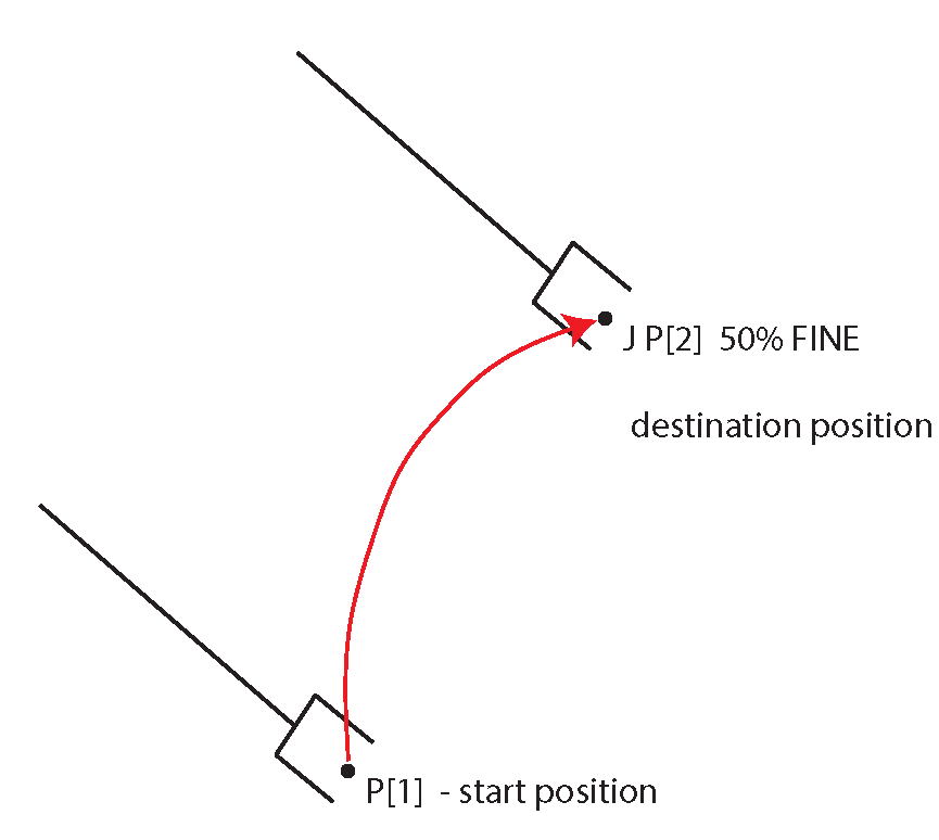
1.) Joint motion that is denoted by “J“. The robot moves to the desired position by moving all axes simultaneously. The motion of every axis starts and completes at the same time instant. The position that is specified is the destination. The speed is specified as a percentage of the total speed or is timed in milliseconds or seconds. The achieved speed is limited by the speed of the slowest axis. The following figure illustrates the joint motion.
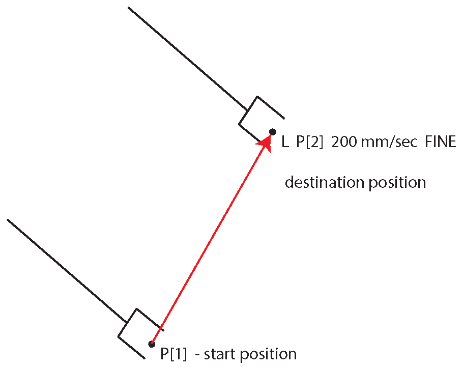
2.) Linear motion that is denoted by “L“. The tool center point (TCP) is moved along a straight line from the start position to the destination position. The code line specifies the destination position. The speed is specified as velocity in millimeters per second, inches per second, etc. The speed can also be timed, as milliseconds or seconds. This motion is illustrated in the figure below.
3.) Circular motion that is denoted by C. The robot moves the tool center point along an arc from the start position through an intermediate position to the destination position.
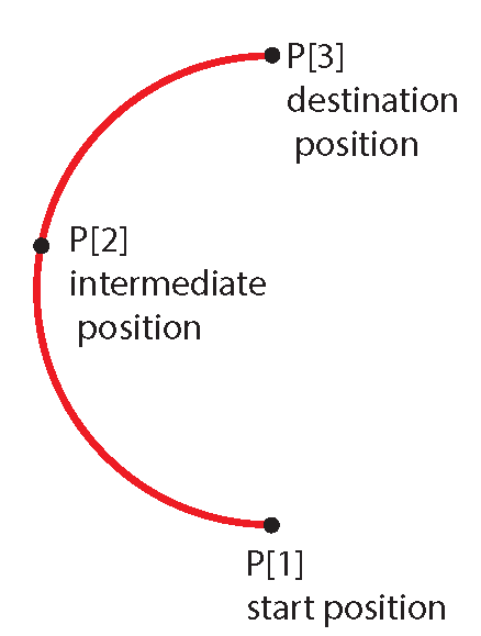
Here is a sample program for half of the circle
1: J P[1] 200 mm/sec FINE
2: C P[2]
P[3] 200 mm/sec FINE