 by
by When designing an object’s shape and dimensions, we need to select the factor of safety. The purpose of the factor of safety is to limit the stress inside of the structure such that it is in the safe operating range. For example, we want stress to be in the elastic region of the stress-strain diagram. Furthermore, we want actual stress to be smaller than the yield stress that will cause plastic deformations.
There are several definitions of the factor of safety. Loosely speaking, the factor of safety can be defined as follows:
(1) 
That is, the factor of safety is the ratio of the critical stress that causes some undesirable behavior to maximal stress that we allow in the structure.
Factor of safety is always larger than 1! The goal of the designer is to choose this factor in order for the structure to safely operate. However, large values of factors of safety will increase the costs, make the structure heavier, and can lead to non-functional design.
The factor of safety should serve as the safeguard against a number of operating conditions, some of which cannot be accurately predicted. The selection of factors of safety should be made on the basis of the following considerations.
- Type of the load. The loads (forces) applied to the structure can be static or dynamics (or the combination of these). In the case of dynamic loads that are periodic, the critical stress (for example a yield stress) can decrease over time if the number of load oscillations is large. This phenomenon is known as fatigue.
- Variations of material properties or parameter variations. Material parameters such as strength (stresses), dimensions, coefficient of thermal expansion, etc. can vary from one segment of a structure to another. Furthermore, during the manufacturing or machining processes material properties can significantly be altered. For example, residual stresses can be induced, or manufacturing errors can introduce stress concentrations.
- Uncertainties in operating conditions. Every designer should know a range of external loads that will be applied to the structure. However, in some cases, unpredictable events can happen or the structure might be subject to the loads that are larger than the expected ones. For example, a failure of one part of the structure, can cause a sudden increase of the loads that will be applied to another part of the structure. Another example is a lifting crane. An operator might try to lift a larger weight than the recommended one. Finally, the structure might operate in unpredictable environment. For example, temperature might be increased or descreased, or external envioronmental factors might influence the structure.
- Theoretical uncertainties. We have developed basic equations for stresses and strains by introducing a number of simplifying assumptions. These assumptions might not be completely accurate, and there is always an error between theoretical predictions and experimental behavior.
- The importance of the member in the overall structure. Some secondary members are designed with lower factor of safety compared to the primary members.
In this brief lecture, our critical stress will be the yield stress. Consequently, the factor of safety is defined by
(2) 
where  is the factor of safety,
  is the yield stress, and
  is the maximal stress that we allow in the structure.
Next, we solve the following simple design example
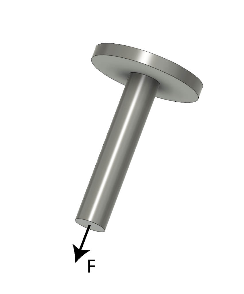
Problem 1: Consider the structure shown in the figure below. Assume that the maximal static force that can be applied to this object is  [N]. Select the material and compute the radius of the cylindrical object such that the structure can safely carry the force
  .
.
Solution:
We have the freedom to select the material. We can select for example structural steel or an aluminum alloy. In practice, the material selection is a critical step and should depend on many factors, such as economical cost, the desired weight of the structure, desired thermo-mechanical behavior, etc. In this example, we select structural steel (A36 steel). According to the datasheet, the yield strength (yield stress) is ![\sigma_{Y}= 250 [MPa]](https://aleksandarhaber.com/wp-content/ql-cache/quicklatex.com-8d3e354e9bfb08754ee2e1ae47018a00_l3.png "Rendered by QuickLaTeX.com") .
.
The next step is to select the factor of safety. In our case, we will select the factor of safety equal to  . This is a simple structure and the basic stress formulas can relatively accurately predict the actual stress, and consequently, there will be no significant uncertainties. Also, we assume that this structure will not be used in demanding applications, or in applications in which the weight of the structure should be minimized (such as for example in aeronautical applications).
From the factor of safety equation, we have
(3)
From this equation, we have
(4) 
On the other hand
(5) 
and since the element is of the circular shape, we have that the cross-section area is  . From the last equation, we have
(6) 
By substituting (4) in the last equation in (6), we obtain
(7) 
Let us substitute the values,
(8) 
The result is
(9) ![\begin{align*}r=0.0160 [m]\end{align*}](https://aleksandarhaber.com/wp-content/ql-cache/quicklatex.com-7cf575728b9dfa4956e0d3053cce3312_l3.png "Rendered by QuickLaTeX.com")
So the radius of the structure should be  , and with the factor of safety , we are convinced that this structure can safely withstand the maximal force of
 ![10^{5} [N]](https://aleksandarhaber.com/wp-content/ql-cache/quicklatex.com-edc44a6a25c63bbb91cfdc27c4d8c3fc_l3.png "Rendered by QuickLaTeX.com") .
.