by
by In this STM32 microcontroller tutorial, we explain how to interface an encoder with an STM32 microcontroller and how to read encoder angle measurements. The YouTube tutorial accompanying this webpage is given below.
Interfacing the Encoder with STM32 microcontroller
In this tutorial, we use a low-cost relative encoder with the product name and number: LPD3806-600BM. The encoder is shown in the figure below.
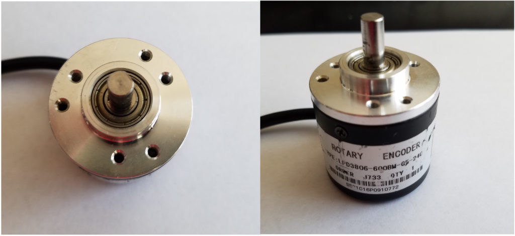
Although we are using this encoder type, everything explained in this tutorial can be applied to other encoder types. The wiring diagram is shown below.
The encoder has 4 wires shown below.
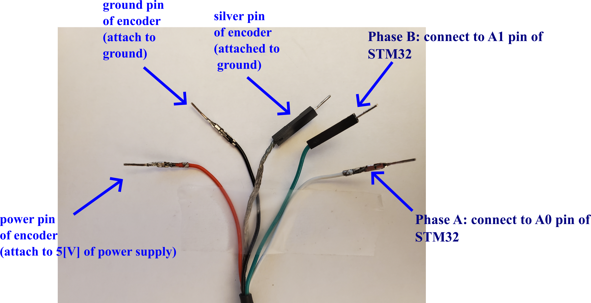
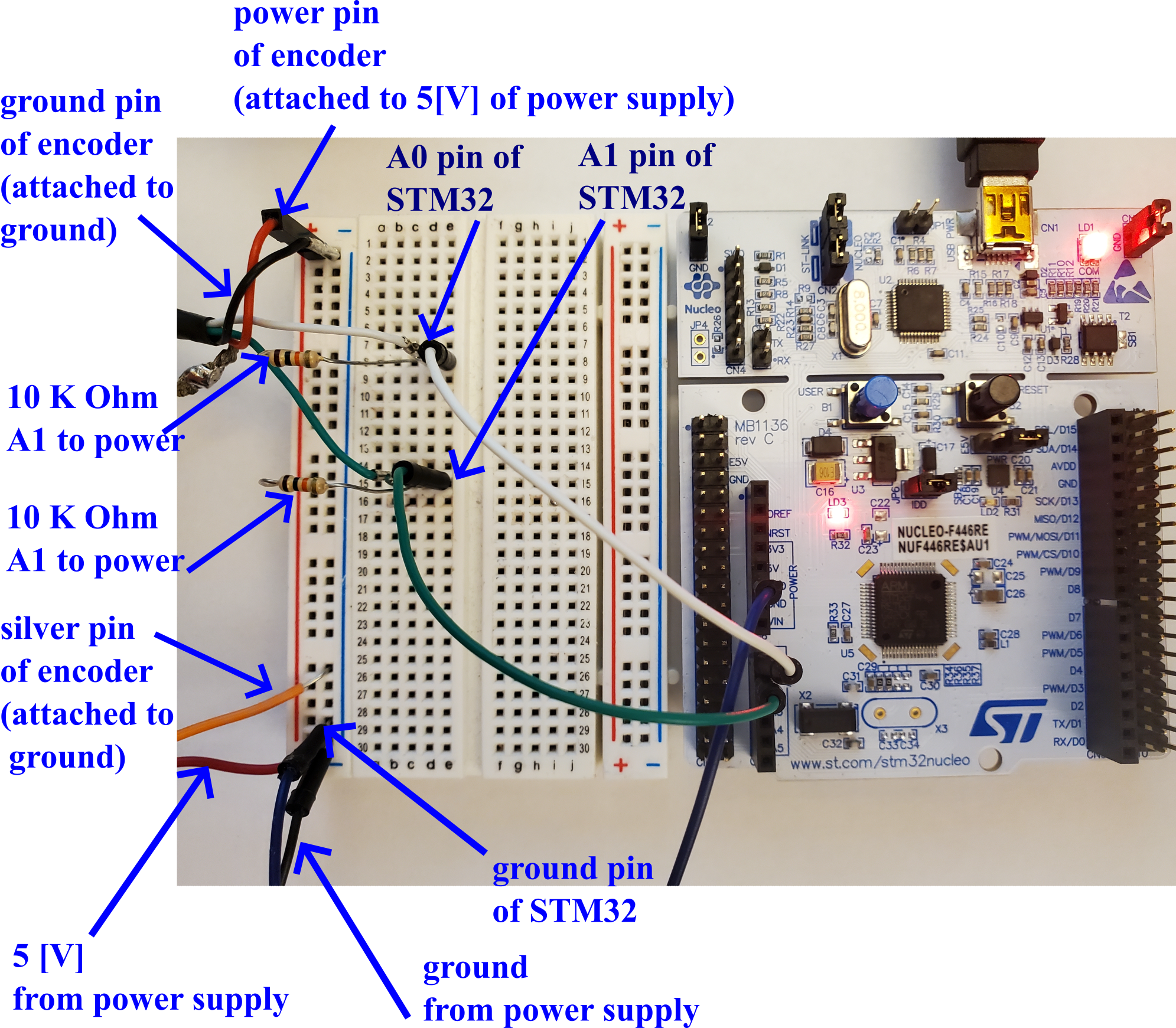
The encoder has 4 wires. The red wire of the encoder should be attached to 5 [V] originating from the power supply. The black wire of the encode should be attached to the common ground of STM32 and the power supply. The silver wire should be connected to the common ground of STM32 and the power supply. The green wire of the encoder should be connected to the A1 pin of STM32. The internal name of this pin is PA1. The white wire of the encoder should be connected to the pin A0 of STM32. The internal name of this pin is PA0.
In Fig. 2, we attach two 10,000 Ohm resistors. These resistors are connected between the power wire of the encoder and the junction point of the pin A0 and A1.
After attaching oscilloscope probes to Phase A and Phase B of the encoder, we obtain the figure shown below.
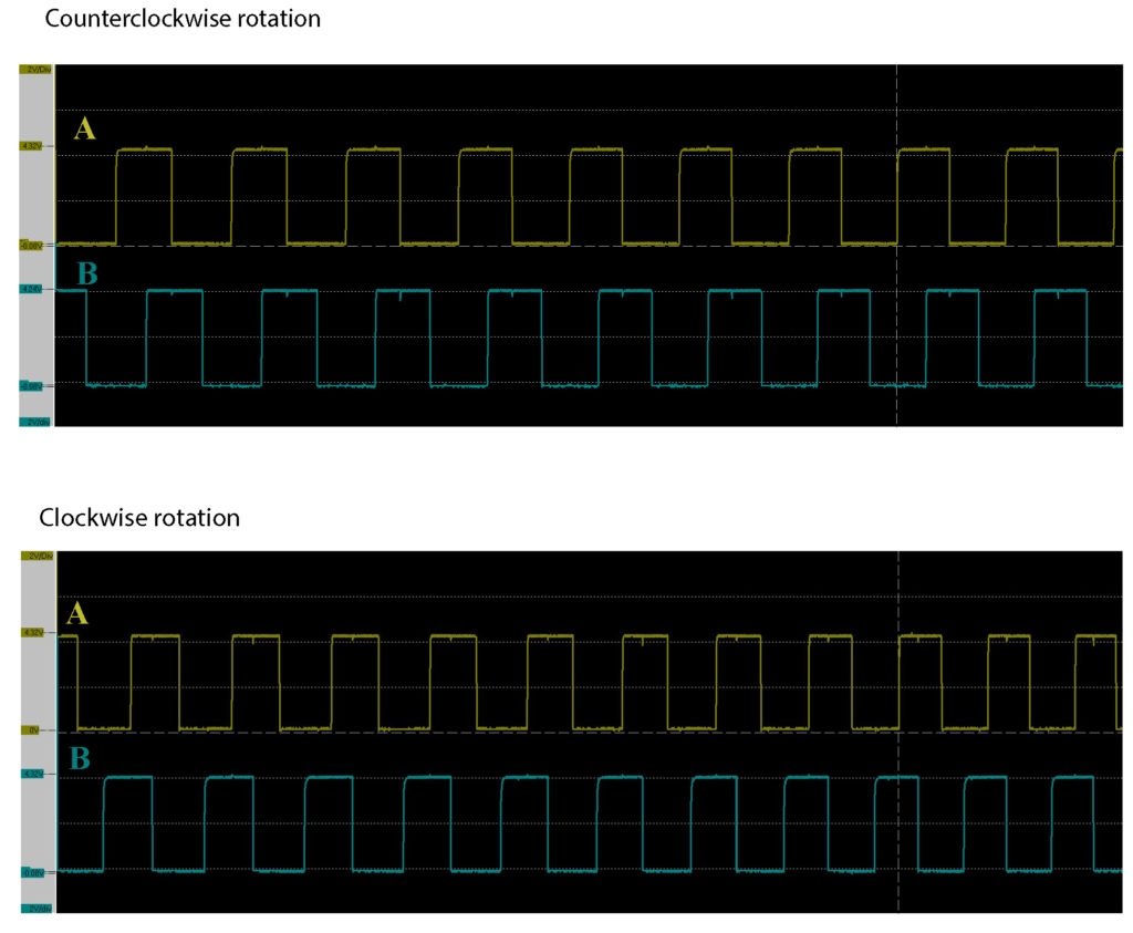
By rotating the shaft of the encoder, pulses on phase A and phase B wires are generated. The pulses are shown in the figure above. The goal is to develop an STM32 code for detecting and counting these pulses. By counting the pulses, we can measure the angle of rotation of the encoder. We can detect and count these pulses by using digital read functions, interrupts, or by using timers. The most elegant, computationally efficient, and easiest approach is to use timers. Consequently, in this tutorial, we use timers to count the pulses.
STM32CubeIDE Modeling
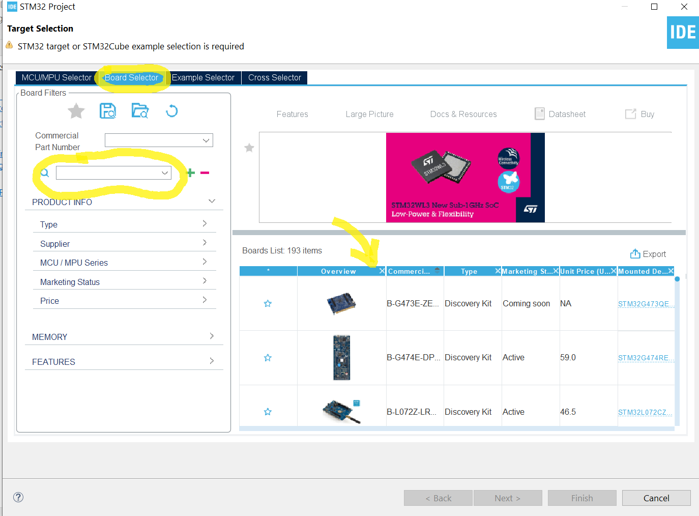
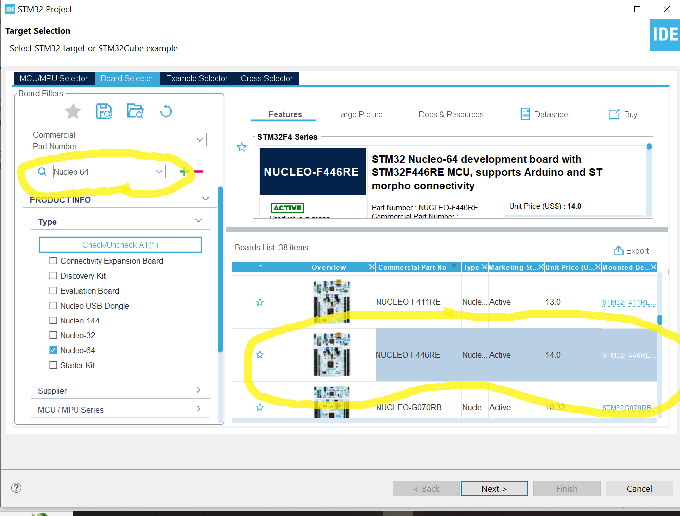
First, we create a new project. Click on File->New->STM32 Project. Then, click on Board Selector, and search for the board name. In our case, we are using a Nucleo-64 board with the product number F446RE.
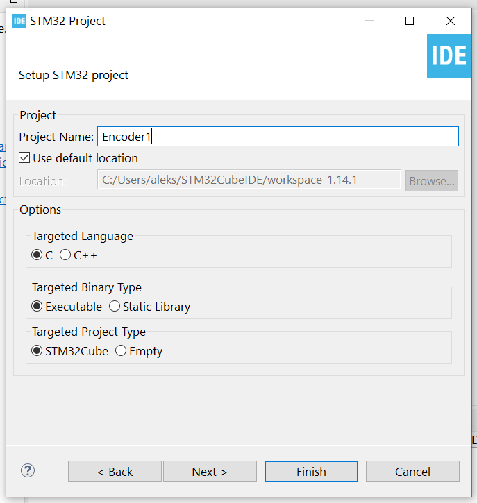
Then, click on Next, and give the project name, and use the default options
Then, click on Finish, and click on Yes, when asked the following “Initialize all peripherals with their default Model?”.
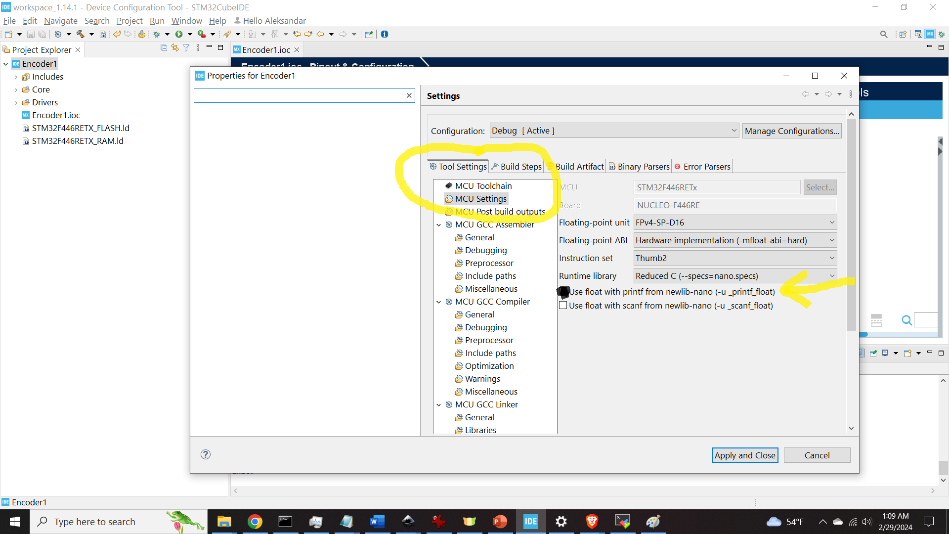
Then, click on the name of the project in the “Project Explorer”. Then, click File and Properties, and then click on Tool Settings, and under MCU Settings, check the button “Use Float with printf from newlib-nano (-u _printf_float)”. This is necessary since we we will print and operate with float numbers in our code.
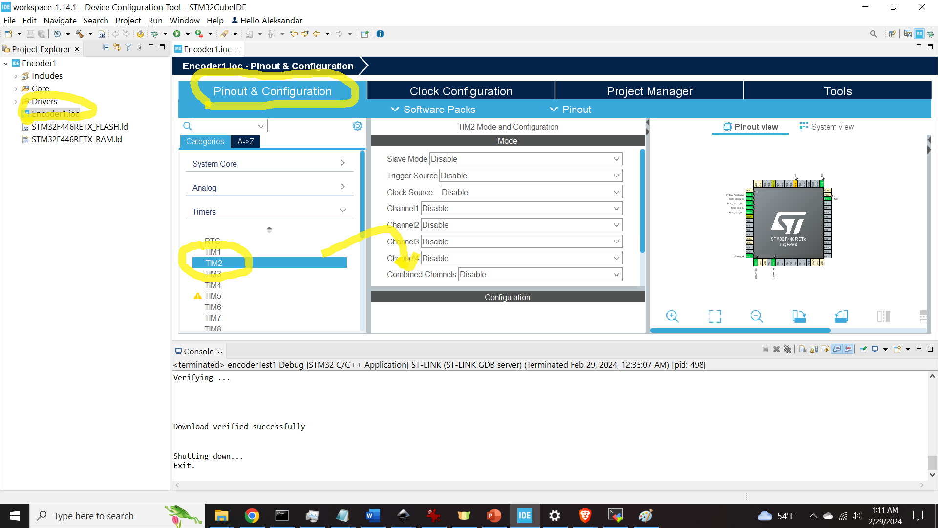
Then, click on “.ioc” file, and click on Pinout&Configuration. In this tutorial, we we will use the timer called TIM2. Click on TIM2 to expand the properties window.
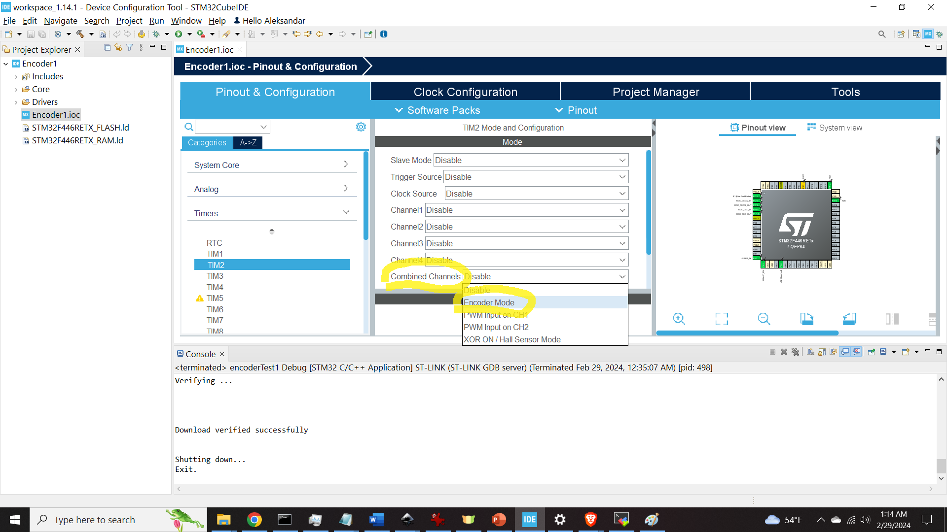
Then, click on Combined Channel and click on Encoder Mode.
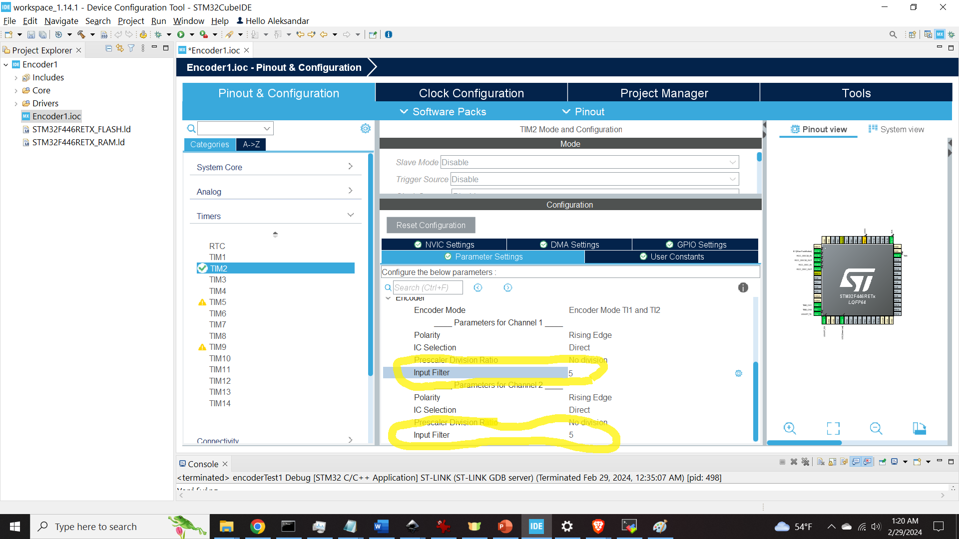
Then, expand the Configuration window, and click on Parameter Settings. Then, click on Encoder mode and click on Encoder Mode TI1 and TI2. This means that we are using an encoder with two channels (phases).
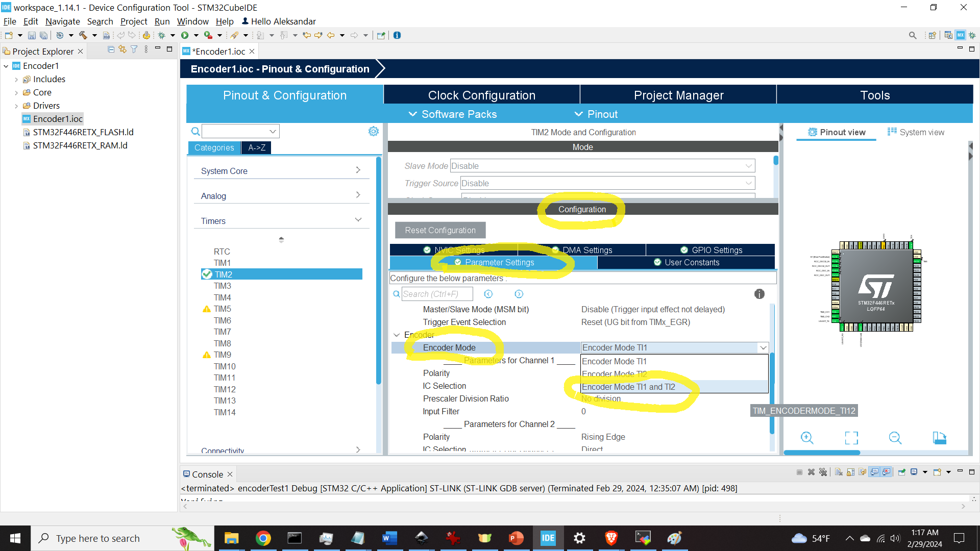
Then, select the filter value for both channels. We use the value of 5, however, you can also experiment with these values.
By expanding the pinout view, you can observe that the timer TIM2 is attached to the pins PA0 and PA1. This is shown in the figure below.
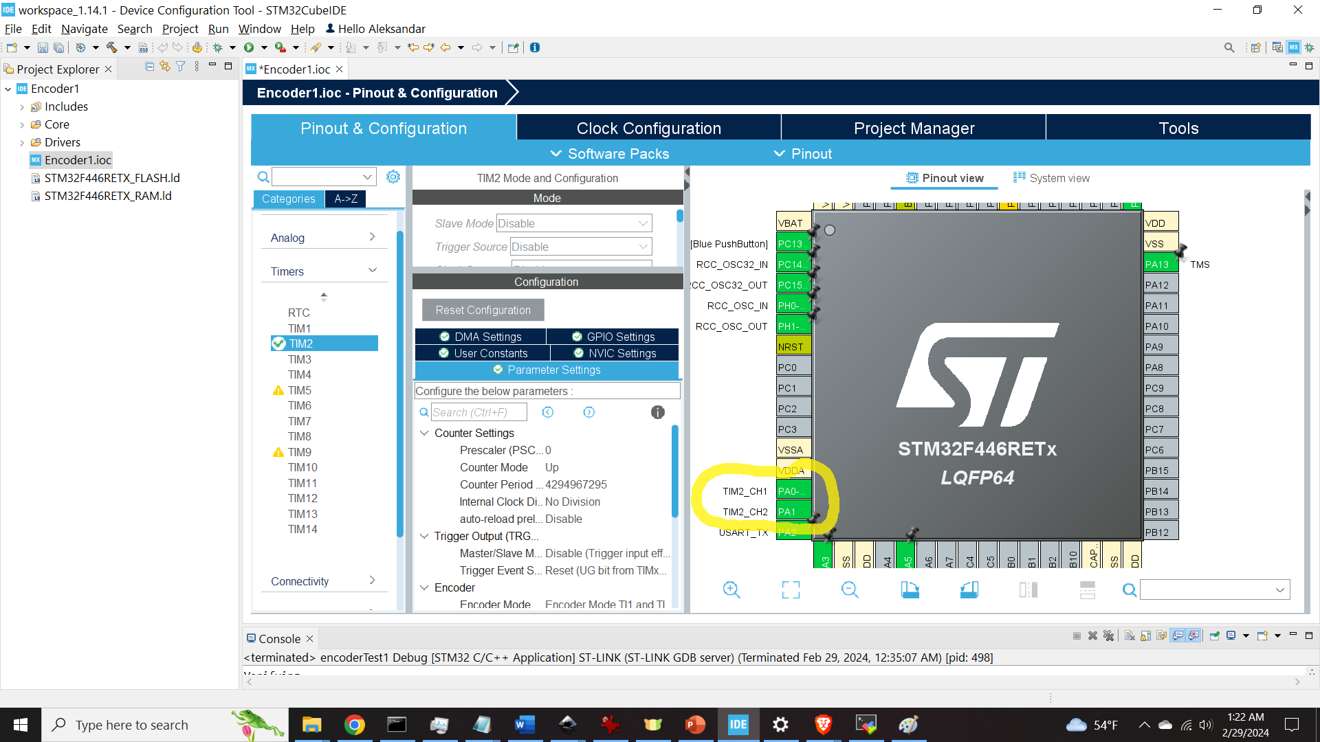
Pins A01 and PA1 are actually pins A0 and A1 pins of the STM32 microcontroller. We figured out this, by looking into the board schematics given here. The main schematics is given below.
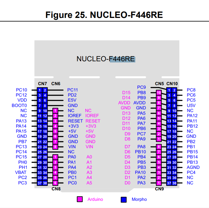
We can see that PA0 and PA1 are A0 and A1 pins. Consequently, we connected the encoder wires to these pins.
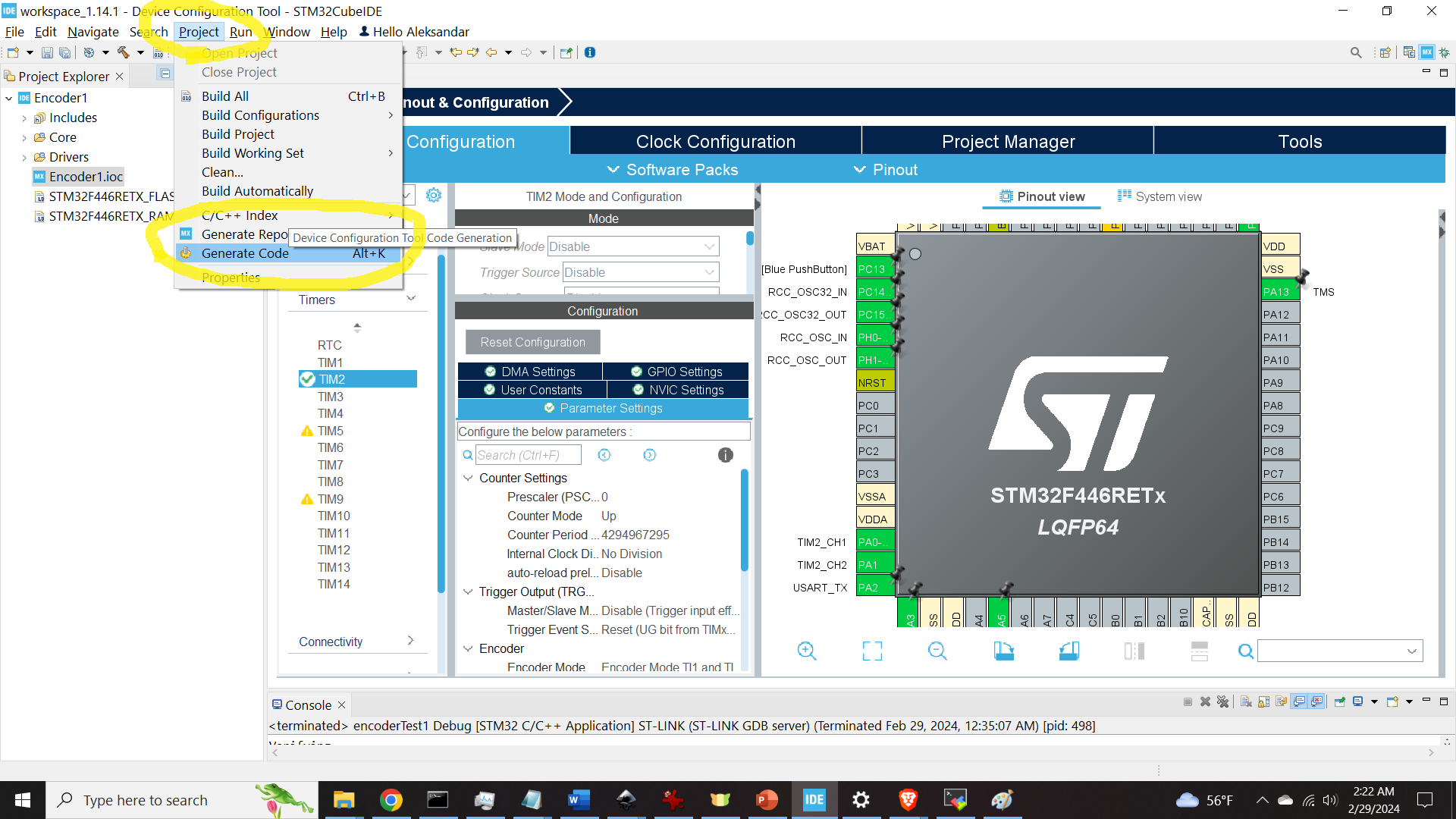
The next step is to generate the C code corresponding to this selection. We can do that by clicking on Project->Generate Code, and then, clicking on YES, as shown in the Figure below.
C Code for Using the Encoder
First, in the main.c file, after the line #include “main.h”, add the following
/* Private includes ----------------------------------------------------------*/
/* USER CODE BEGIN Includes */
#include <stdio.h>
/* USER CODE END Includes */
Then, in the main.c file, after “MX_TIM2_Init();”, add the following
 /* USER CODE BEGIN 2 */
  int counterValue = 0;
  int pastCounterValue = 0;
  float angleValue=0;
  char printMessage[200]={'\0'};

  HAL_TIM_Encoder_Start(&htim2, TIM_CHANNEL_ALL);
  /* USER CODE END 2 */
Then, in the while loop add the following
    /* USER CODE BEGIN 3 */

	  counterValue = TIM2->CNT;
	    if (counterValue != pastCounterValue)
	    {
	    	angleValue=(360.0/2400.0)*((float)counterValue);
	    	sprintf(printMessage, "Current angle is: %f\n\r", angleValue);
	    	HAL_UART_Transmit(&huart2, (uint8_t*)printMessage,sizeof(printMessage), 300);
	    }
	    pastCounterValue = counterValue;
Building and Uploading the Project to STM32 Microcontroller and Testing the Encoder Readings
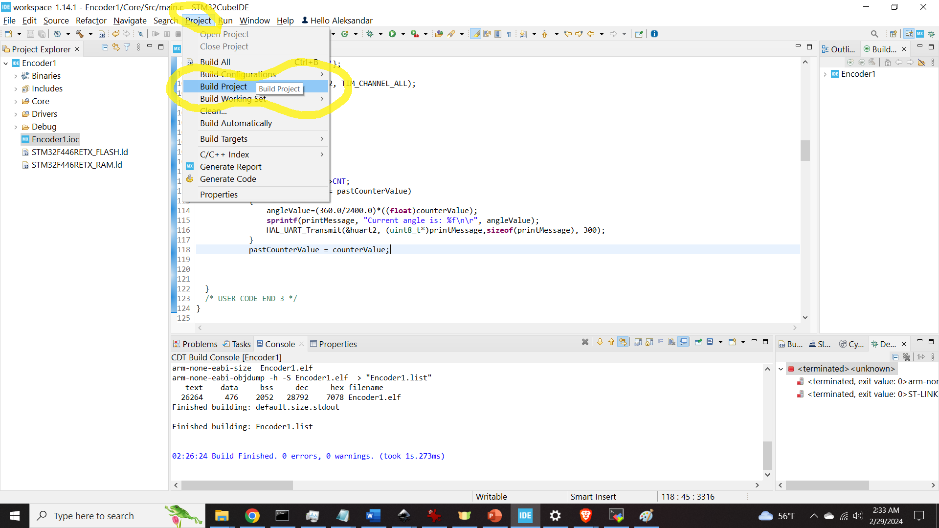
To build the project, you need to click on Project, and then on Build Project.
To run the project, you can click on the green play button as shown in the figure below.
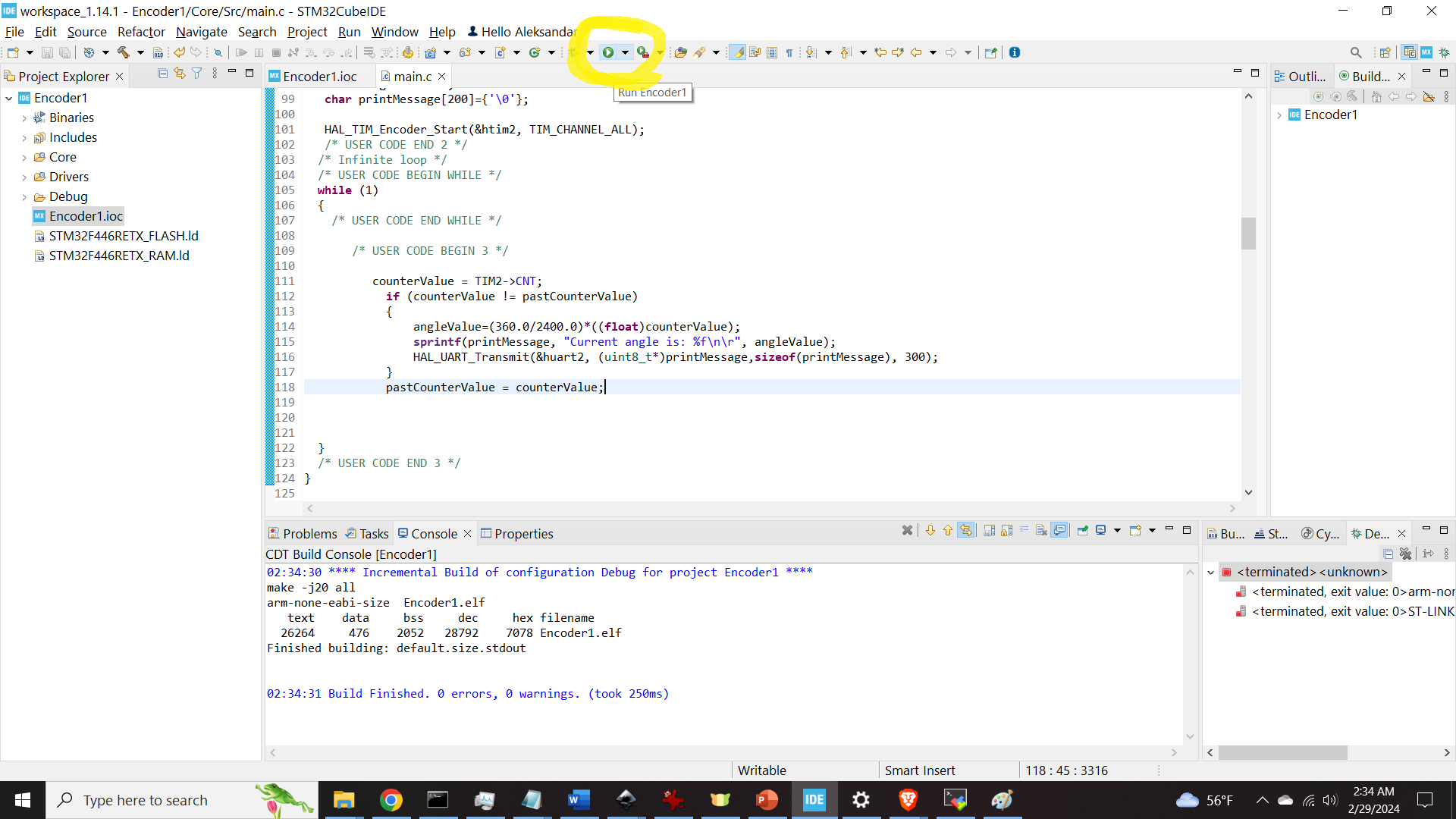
After that, the screen shown below will appear
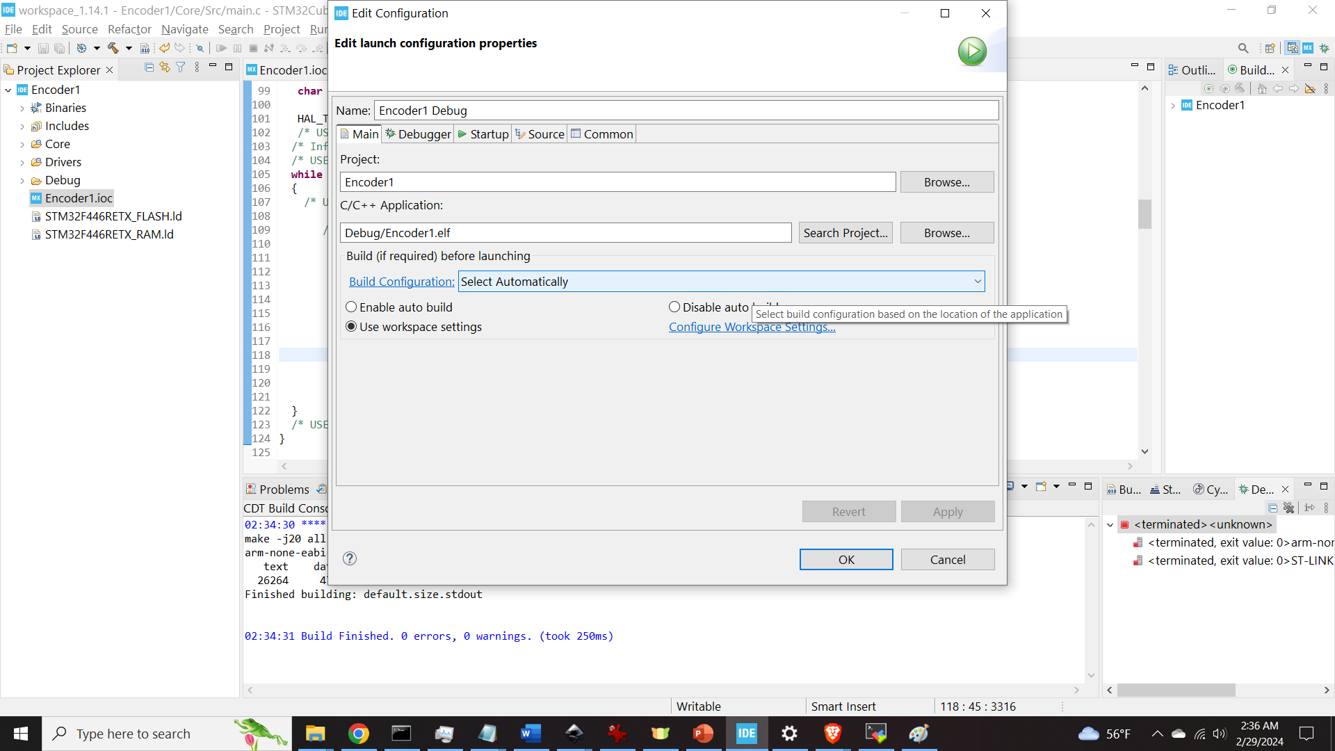
Click on OK to use the default settings.
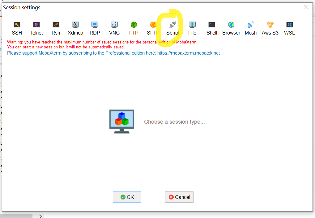
Next, we need to test the encoder readings. To test the encoder readings, we need to establish a serial communication link between the computer and the microcontroller. We can do that by using a program called MobaXterm. It is free software that for establishing SSH and serial communication between computers and external devices. Open MobaXterm and click on Session as shown in the figure below.
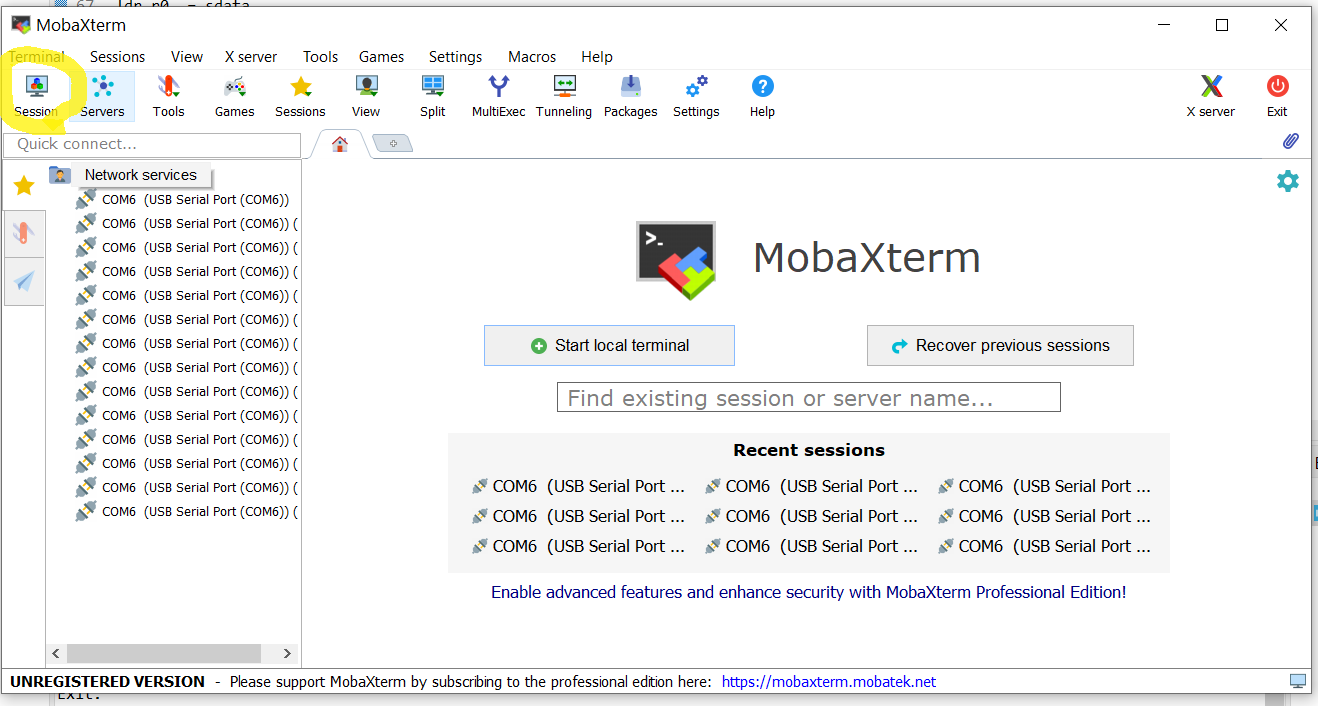
Then, click on Serial
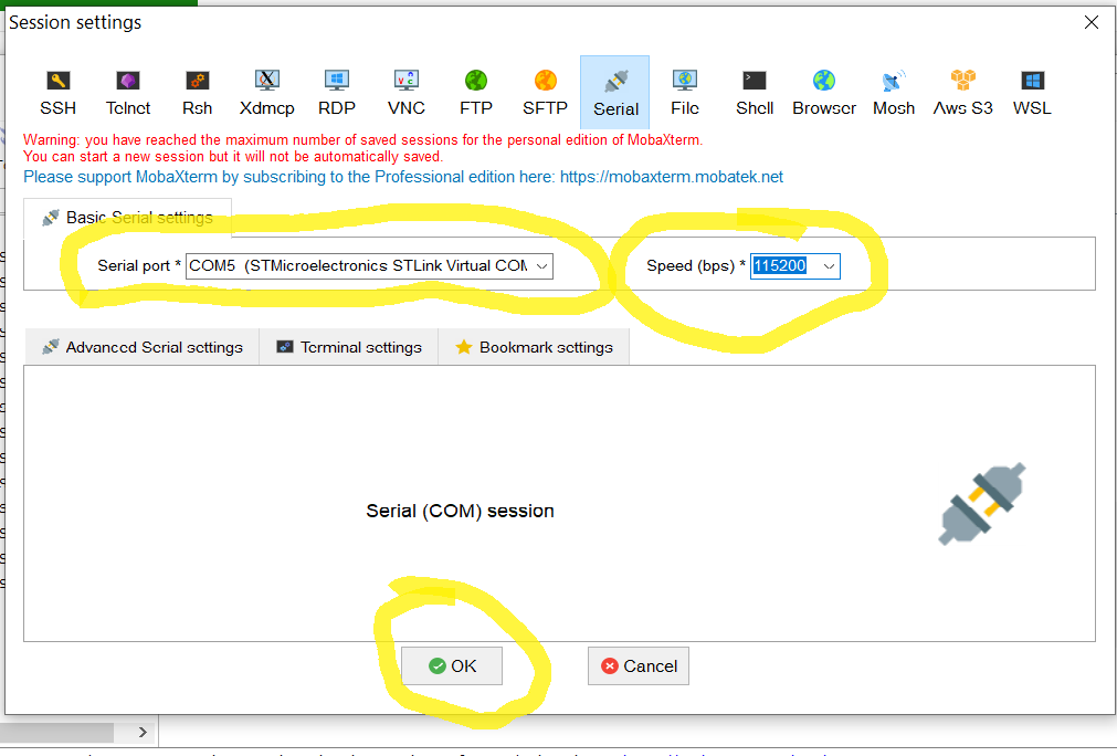
and select the proper COM port to which STM32 is attached and select the speed. By default UART communication is set to 115200 in STM32, and consequently, you need to use this speed in MobaXterm. Then, click on OK.
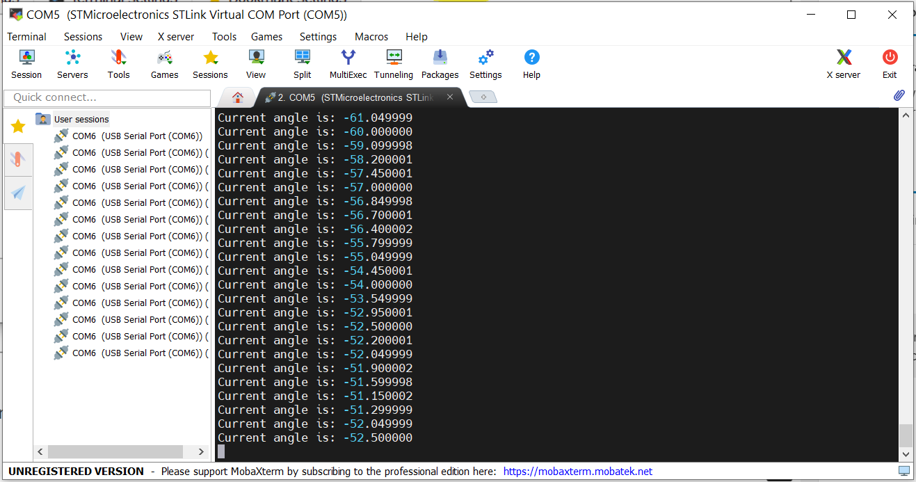
By clicking on OK, the serial terminal should open and you should see the encoder readings which are shown in the figure below.