 by
by In this tutorial, we explain how to properly configure and use interrupts in STM32 microcontrollers. Interrupts are very important components of microcontrollers which enable us to temporarily interrupt the code that is currently running and to run another function or piece of code that can handle an external event. For example, in mechatronics and control systems, interrupts can be used to read and process encoder pulse readings.
Circuit for Demonstrating Interrupts
To demonstrate how to use interrupts, we created a simple circuit shown in the figure below.
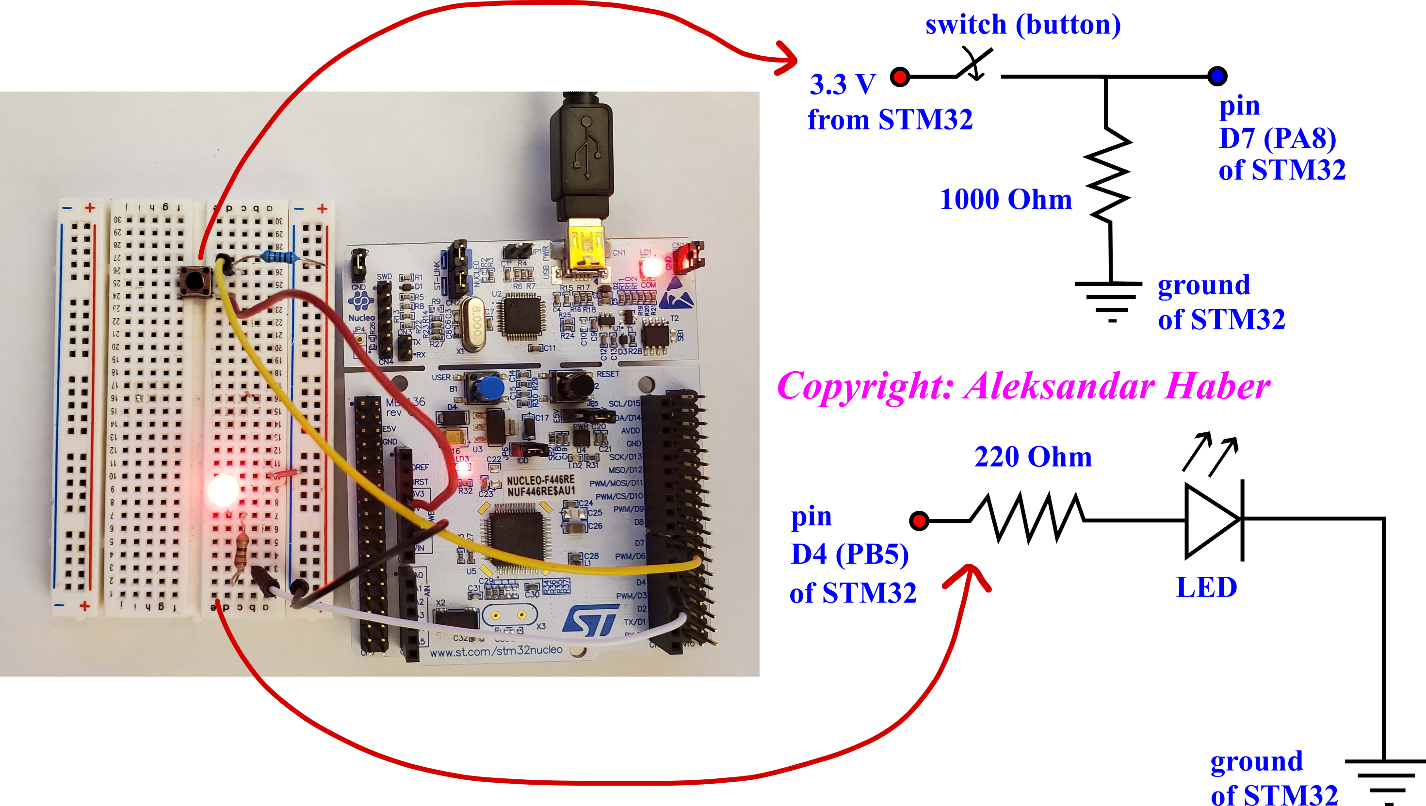
We are using a Nucleo-64 board (F446RE). This circuit will turn on or off an LED (light emitting diode) by pressing the button (switch). If we press the button the LED will turn ON. Then, if we press the button again, the LED will turn OFF. This is achieved by assigning the interrupt to the pin attached to the button. If the interrupt pin detects a rising edge, then the current execution of the code will stop, and an interrupt function is called. This function is called the interrupt handler or Interrupt Service Routine, which is abbreviated as ISR. The interrupt handler function sends high or low voltage to the pin that is attached to the LED and the resistor that limits the current through the LED.
First, let us briefly describe the button circuit. One port of the button is attached to the 3.3 V power pin of the STM32. The other port of the button is attached to the pin D7 of the STM32. Pin D7 is internally denoted by PA8 (Port A, pin 8) in the board manual. We use a 1000 Ohm resistor as a pull-down resistor. We use the ground of STM32. Next, we describe the LED circuit. One port of the LED circuit is attached to the pin D4 of STM32. Pin D4 is internally denoted by PB4 (Port B, pin 5) in the board manual. We use a 220 Ohm resistor to limit the current through the diode. The circuit is grounded to the STM32 ground.
Once the button is pressed, the pin D7 will detect 3.3V. Then, the rising voltage edge will be detected by the interrupt. After that, the interrupt function will be called. This function will either send the low or high voltage to the output pin D4 (PB5) of STM32, depending on the previous value of voltage. This function will be explained later on in the tutorial.
Note here that for the simplicity and brevity of this tutorial, we did not implement a button debouncing mechanism. This mechanism can be implemented in software or by designing a simple capacitor-resistor circuit.
STM32 Implementation of Interrupts
The code that implements the interrupt callback function is given below.
/* USER CODE BEGIN 0 */

GPIO_PinState pinState=1;

// Interrupt callback function
void HAL_GPIO_EXTI_Callback(uint16_t GPIO_Pin)
{
    if(GPIO_Pin == GPIO_PIN_8)
    {

		HAL_GPIO_WritePin(GPIOB, GPIO_PIN_5,pinState);
		if (pinState==0)
		{
			pinState=1;
		}
		else
		{
			pinState=0;
		}


    }
}


/* USER CODE END 0 */
The code is self-explanatory.