 by
by
In this tutorial, we explain how to control Drone and Quadrotor DC motors by using Teensy/Arduino microcontrollers and Pulse Width Modulation (PWM) signals. The YouTube video accompanying this tutorial is given below.
Experimental Setup
The experimental setup is shown below.
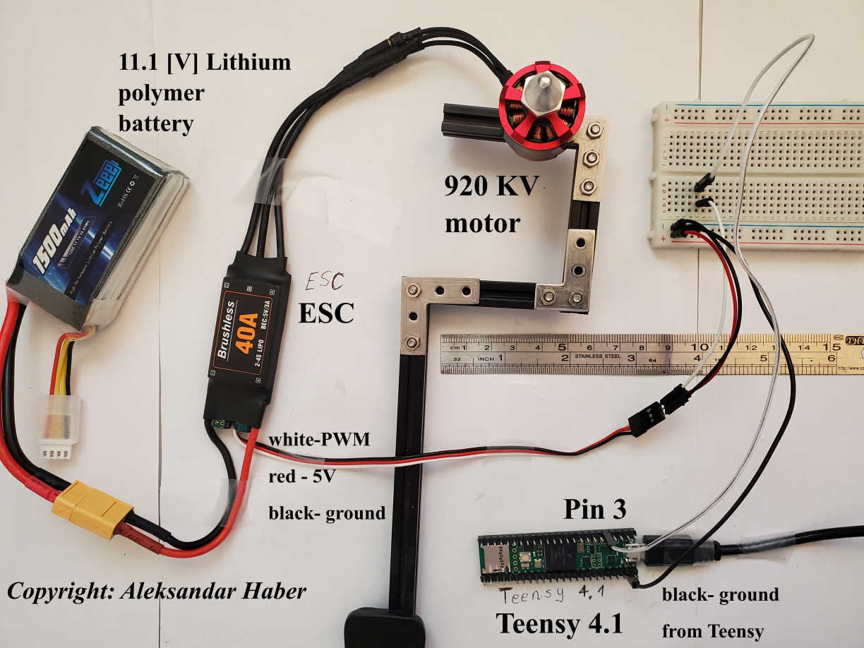
It consists of:
- Teensy 4.1 microcontroller. In this tutorial series, we use the Teensy microcontroller. The code for controlling the Teensy microcontrollers is almost identical to Arduino code, and consequently, everything explained in this tutorial can easily be generalized to Arduino microcontrollers.
- Electronic Speed Controller – or briefly ESC. This is a motor driver. Currently, we are using a 40 [A] (amperes) ESC. This motor driver contains a separate circuit called BEC, which is an abbreviation for a battery elimination circuit. Essentially, the BEC serves as a voltage regulator that steps down the LiPo battery from 11.1 [V] to 5 [V]. BEC enables us to power up a microcontroller or some other devices, such as servo motors by using the main LiPo battery. In this way, we do not need to have a separate battery for our microcontroller or some other electronic or electro-mechanical devices on our quadrotor. We are using a low-cost 40 [A] ESC available on Amazon. Unfortunately, this battery does not have specifications available online. However, everything explained in this tutorial can be generalized to other ESCs.
- 920 KV DC brushless motor. In this tutorial, we use a low-cost “ReadytoSky” motor. The motor velocity constant is denoted by KV. In our particular case, 920KV means that if we provide 1 V to the motor, the motor will spin with the angular velocity of 920 RPM. On the other hand, the nominal battery voltage of 11.1 V will sping the motor with the angular velocity 10212 RPM. That is approximately 170 revolutions per second.
- Lithium Polymer battery with a capacity of 1500 mili-amper-hours, or briefly mAh. The Lithium polymer battery is abbreviated as LiPo. Our battery has a voltage rating of 11.1 [V]. It has 3 cells. Every cell provides 3.7 volts. If we multiply 3 by 3.7, we obtain 11.1. [V].
- Breadboard and connecting wires.
The connecting diagram is simple. The ESC has three connection ports. The first connection port is connected to the LiPo battery. The second port containing three connectors is connected to the motor. The third (low-current) connector consists of three wires:
- The black wire is the ground wire of BEC.
- The red wire is the constant 5 [V] wire of BEC. Black and red wire can be used to power up the microcontroller or other electrical or electromechanical devices.
- The white wire is the Pulse Width Modulation (PWM) signal wire. This wire is connected to the pin 3 of the Teensy microcontroller. The Teensy microcontroller generates the PWM signals and through the pin 3 and breadboard interface, sends these signals to the PWM wire of ESC.
Also, the ground of the Teensy microcontroller should be connected to the common ground on the breadboard. Also, the ground wire of the BEC should be connected to the common ground on the breadboard. That is, both the ground of Teensy and BEC should be connected to each other.
Control of Motors
Unfortunately, for the particular ESC we are using, we were not able to find the exact specifications. Fortunately, the ESC we are using is not significantly different from similar ESCs available online. Consequently, we searched for specifications of similar ESCs available online. We obtained the following information which is also confirmed by experiments.
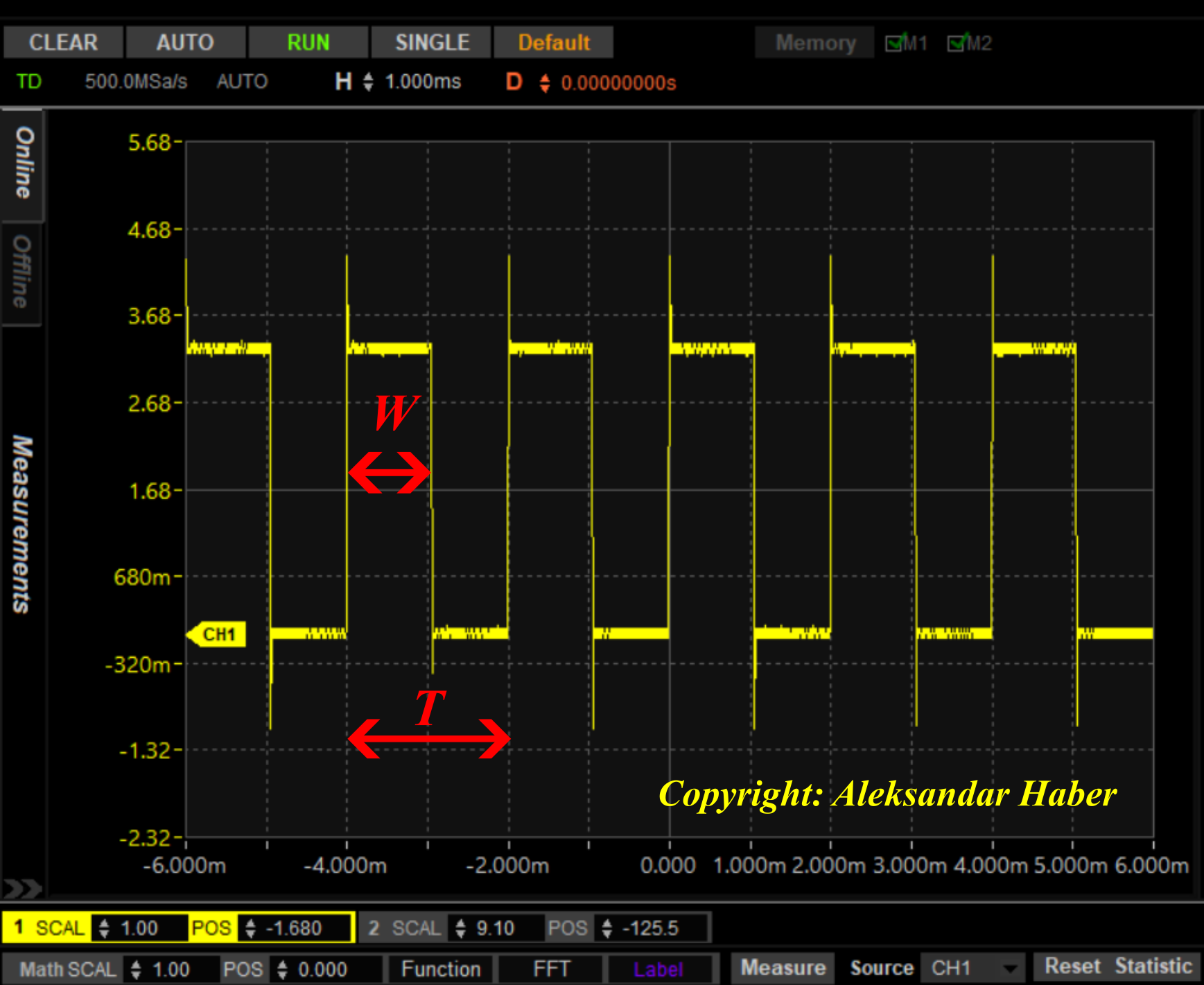
First of all, the DC drone motors are controlled by using Pulse Width Modulation (PWM) signals. The PWM signals are quantified by the period or frequency of the PWM signal, and the width of the pulse in the PWM signal. The period, denoted by  , and the pulse width, denoted by
  , are shown in the figure below.
 and the pulse width .
According to the information found in manuals of ESC motor drivers, the pulse width for controlling the motor should be in the interval from 1 millisecond to 2 milliseconds. Here, 1 millisecond should produce the lowest possible motor angular velocity, and 2 milliseconds produce the highest possible motor angular velocity allowed by the motor driver. Any pulse width between 1 and 2 milliseconds will produce the motor angular velocity between the minimum and maximum values. The duty cycle  is defined by the following ratio
(1) 
We discovered that in practice, the start and end values of the interval do not exactly correspond to 1 and 2 milliseconds. There are small deviations from these values. On the other hand, we also have the freedom to select the frequency of the PMW signal. That is, we have the freedom to select the period of the PWM signal. In our experiments, we use a frequency of 500 Hz. This is mainly because this frequency corresponds to the period of the PWM signal of  seconds (2 milliseconds). That is, the motor will be started at approximately 50 percent of the duty cycle, and the maximal angular velocity will be reached at 100 percent of the duty cycle. It is also possible to select the lower frequency of the PMW signal. For example, in the range of
  to
to  Hz. However, for the values of the PWM frequency lower than Hz, we might have a saturation limit. This is mainly because the motor will not spin faster for pulse widths larger than 2 milliseconds. We might send a pulse that is larger than 2 milliseconds, however, this might not increase the motor’s angular velocity. In fact, we discovered that pulse widths larger than 2.5 or 2.6 will actually stop the motor. Consequently, it might be a good idea to use the frequency of 500 Hz or to use a lower frequency, however, in that case, we need to limit the pulse width to 2 milliseconds.
The Teensy/Arduino code for controlling the motor is very simple
void setup() {
analogWriteFrequency(3,500);
analogWriteResolution(8);

}

void loop() {
    analogWrite(3,150);
}
In the setup function, we use the function “analogWriteFrequency()” to specify pin 3 as the output pin, and we set the PWM frequency of 500 Hz. Then, we specify the resolution of 8 bits for defining the pulse width. This is done by using the function “analogWriteResolution”. This corresponds to the digital range from 0 to 255. Zero corresponds to the pulse of the zero width, and 255 corresponds to the pulse of the width of 255*(1/(256*500)). This produces the maximum pulse width of 2 milliseconds. The value between 0 to 255 is our control signal. Let this control signal be denoted by  . Then, the pulse width is
(2) 
In the case of our motor and the driver, we experimentally discovered that the motor starts at the control value of  . This corresponds to the pulse width of
  milliseconds, which is approximately
  milliseconds. This is in agreement with the information found in manuals. In our infinite void loop, we use the function “analogWrite()” to send the PWM signals to pin 3. That is, the first input argument of this function is the pin number and the second input argument is the value of the control signal in the interval from 0 to 255.
Depending on the ESC driver, the starting pulse width and the end pulse width, defining the control range, might not be exact. For example, it might happen that the motor starts at 1.1 milliseconds and that it stops at 1.9 milliseconds pulse widths. Consequently, these numbers need to be calibrated. Here is the ESC motor driver calibration procedure that works in our case (in your case, if you have the ESC manual, read the manual for the exact calibration procedure).
- Connect the ESC to the microcontroller, however, do not power up the ESC. That is, disconnect the ESC from the battery.
- By using the function analogWrite() in the main loop of the code, send the maximal pulse width. That is, modify the arguments of the analogWrite function as follows “analogWrite(3,255)”. Upload the code.
- Then, power up the ESC driver by attaching the battery to the driver. After you power up the ESC driver, you will hear the beep-beep sounds or a similar high-pitched melody. This melody is actually produced by the motor and is created by the motor driver by sending a high-frequency signal.
- After you hear the sound, send the pulse width the width that is approximately 1 millisecond. You can do that by modifying the analogWrite function as follows “analogWrite(3,127)”. Then, upload the code. After that, you will hear another beep sound. This means that the ESC driver is calibrated.
- Then, test the calibration by trying to run the motor by using “analogWrite(3,136)”.
The calibration video tutorial is given below.