 by
by In this mechatronics and control engineering tutorial, we explain how to control DC motors by using STM32 microcontrollers. We explain how to control the speed and the rotation direction of a DC motor. The YouTube video accompanying this tutorial is given below.
Experimental Setup Description
The experimental setup is shown in the figure below.
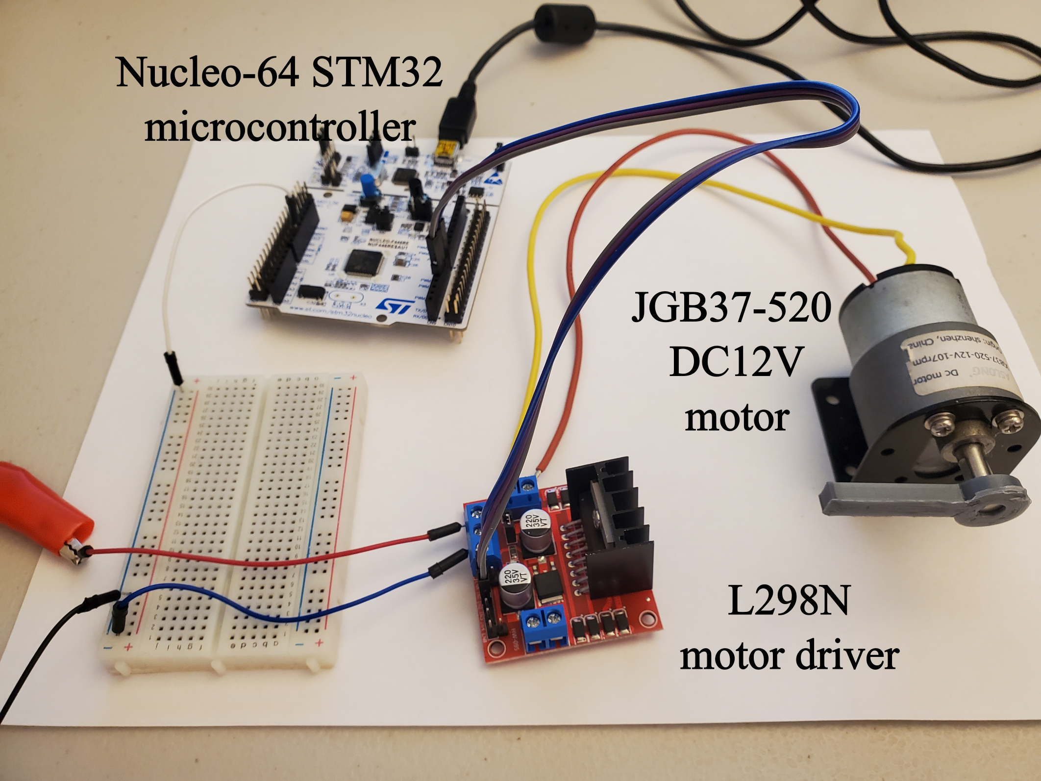
The setup consists of
- L298N motor driver
- JGB37-520 DC12 motor (or any other DC motor). This is a brushed DC motor, with a voltage range of 12-24 [V].
- Nucleo 64 STM32 microcontroller (board number NUCLEO-F446RE)
- DC power supply
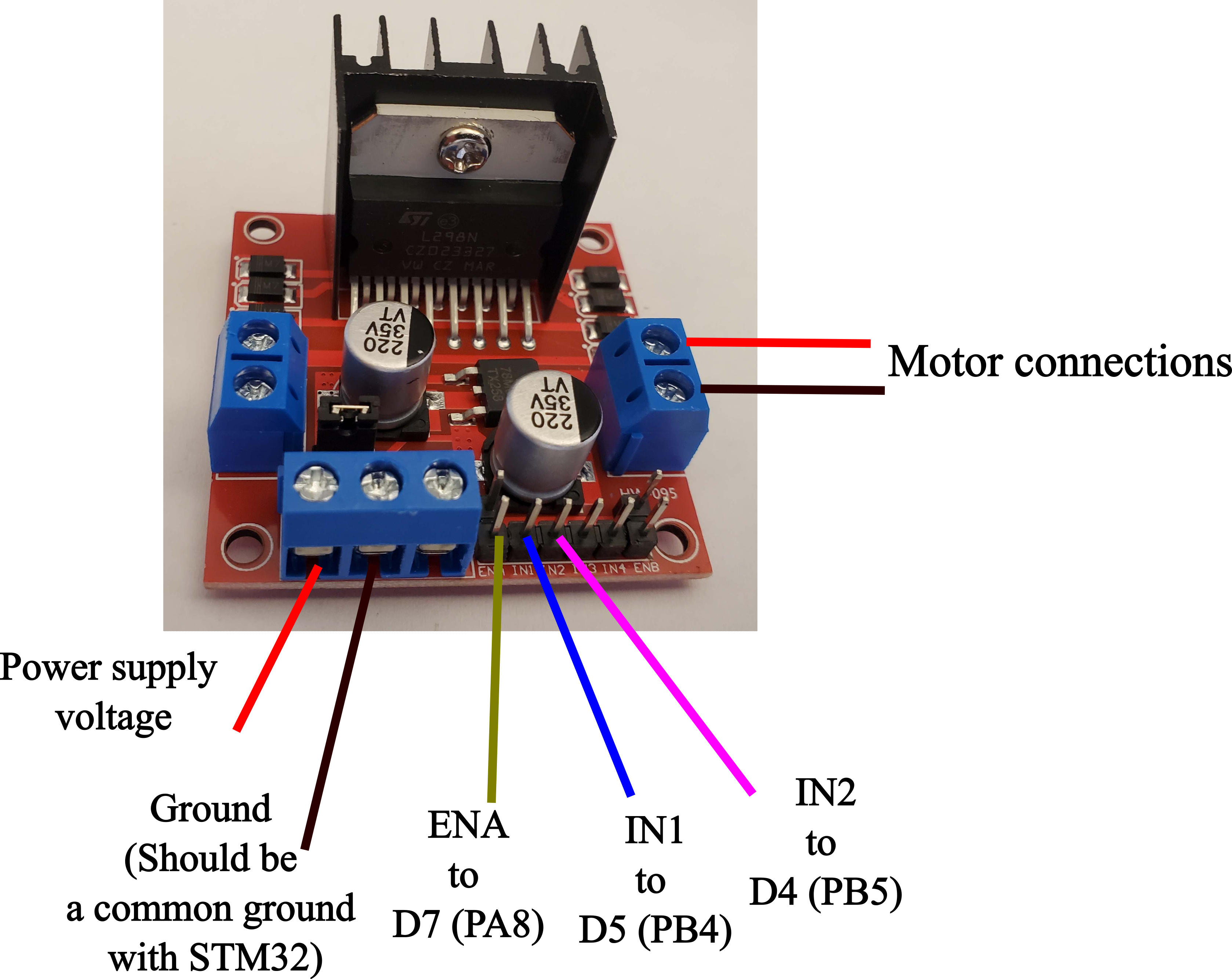
The connection diagram for the L298N motor driver is shown below.
The pin and connection diagram of the STM32 Nucleo-64 board is shown below.
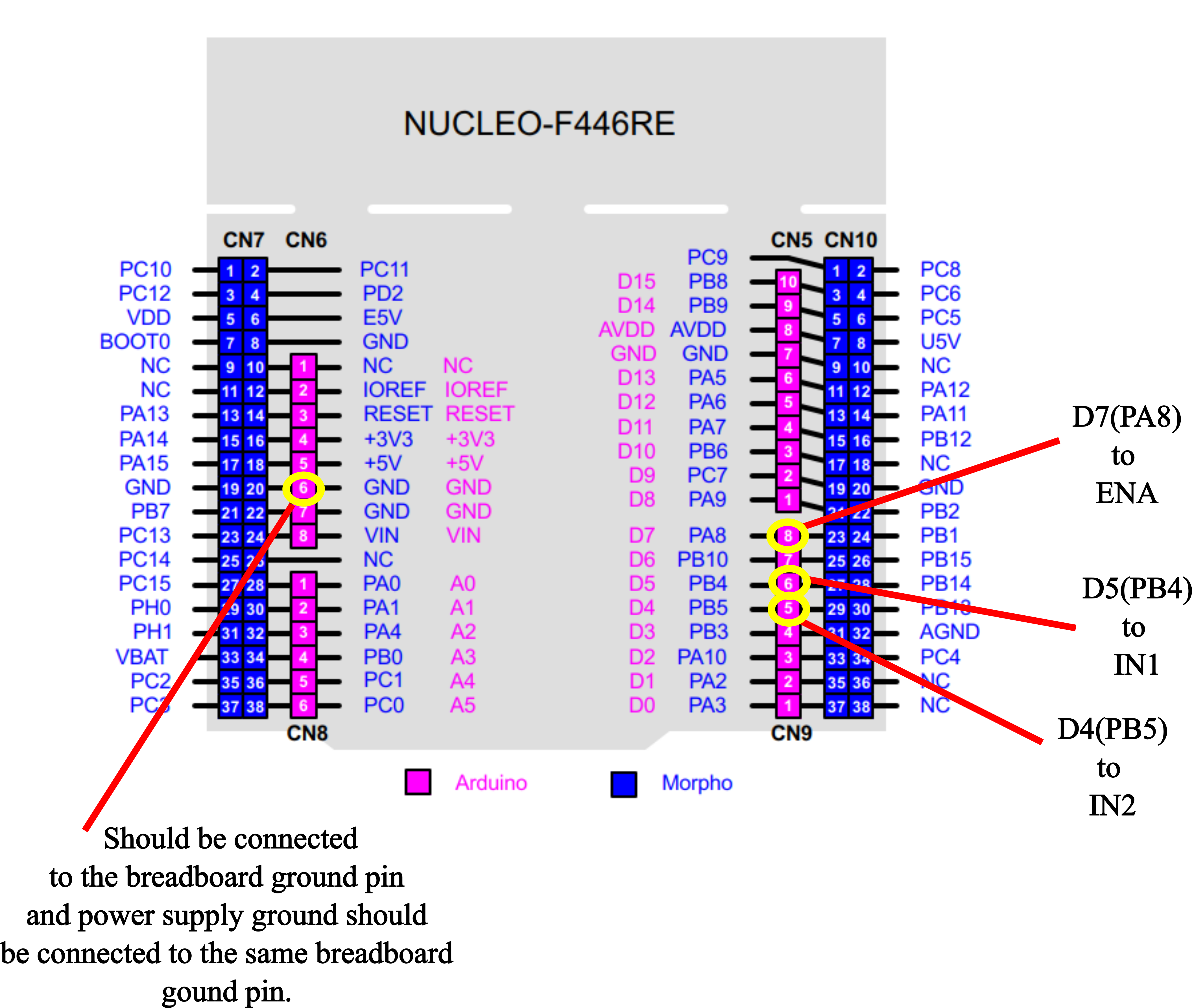
The motor driver received the Pulse Width Modulation (PWM) signal from the PIN D7 (PA8) of the STM32 Microcontroller. This pin is connected to the PIN ENA of the motor driver. The STM32 pins D5(PB4) and D4(PB5) are connected to the PINs IN1 and IN2, respectively, of the motor driver. The PINs IN1 and IN2 are digital pins that are used to control the direction of the motor as follows:
- IN1:LOW and IN2:LOW – motor OFF
- IN1:HIGH and IN2:HIGH – motor OFF
- IN1: HIGH and IN2:LOW – motor ON and forward rotation
- IN1: LOW and IN2:HIGH – motor ON and backward rotation
Code for Controlling the Motor
In our previous tutorial, given here, we explained