 by
by
In this post, we explain how to connect a low-cost incremental rotary encoder (LPD3806-600BM) to a Raspberry Pi microcontroller. We provide detailed instructions with a C/C++ code. The encoder is shown in Fig.1 below.
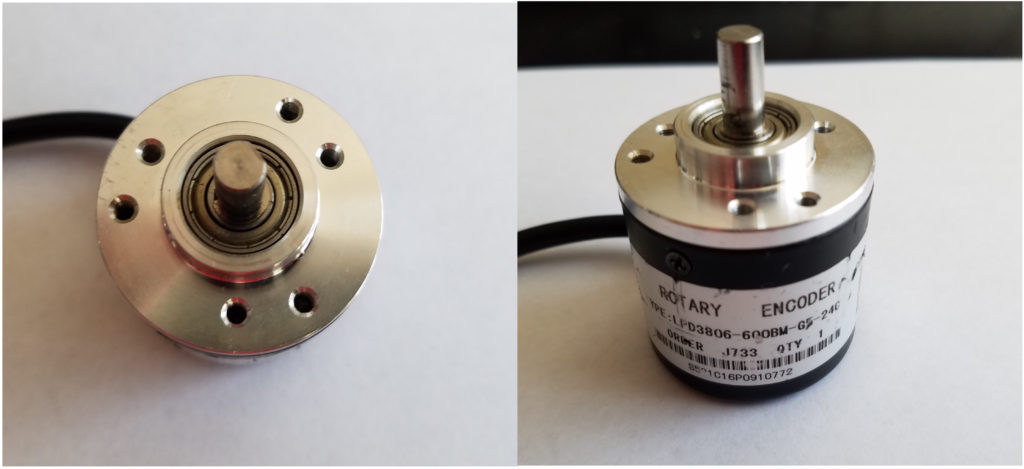
Rotary encoders are used in mechatronics and mechanical systems for measuring the angle of rotation of rotating objects, such as motor shafts, gears, etc. The working principle of relative encoders is explained here. In our case, we are dealing with an incremental encoder. This encoder type provides an angle measurement that is relative to the starting angle (angle of the main shaft at which we started our measurements). By using the homing strategy we can also measure the absolute angle/position using incremental encoders.
The wiring diagram of the incremental encoder is shown in Fig. 2 below.
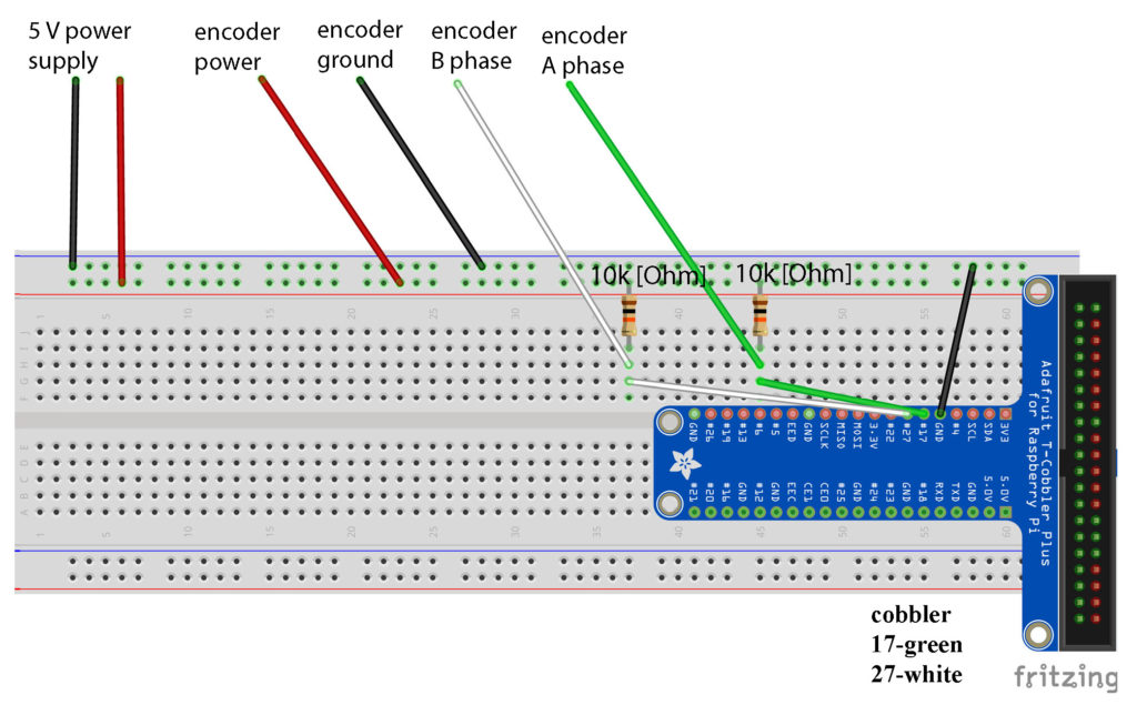
The encoder has 4 connections: power, ground, phase A, and phase B. The power ground should be connected to an external power source (do not use the internal Raspberry Pi power pin). The power source, encoder, and Raspberry Pi should have a common ground. The phase A and phase B connections should be connected to the 17 and 27 cobbler pins (GPIO pins).
Two ![10 [k \Omega]](https://aleksandarhaber.com/wp-content/ql-cache/quicklatex.com-761e815a0d2bffeed90c96a466308df0_l3.png "Rendered by QuickLaTeX.com") pull-up resistors should be connected to the power and phase A and phase B connections.
pull-up resistors should be connected to the power and phase A and phase B connections.
The figure below shows the voltage readings between phase A (phase B) and the ground for counterclockwise and clockwise rotations of the encoder shaft.
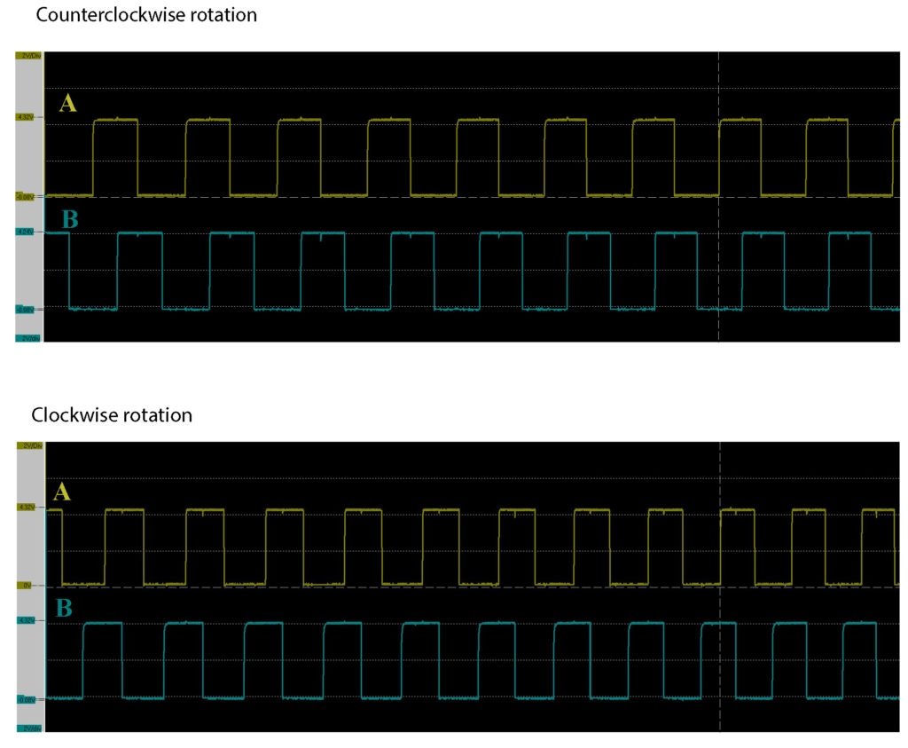
We can observe that in the counterclockwise case, phase A leads the phase B. On the other hand, in the clockwise direction phase B leads the phase A. This is an important observation that enables us to develop the C/C++ code for measuring the rotation angle.
We can introduce two states for phases A and B. The state of phase A (phase B), denoted by “phase A” (“phase “), can be 0 or 1. The zero state corresponds to a low volage value (0 [V]), and the high voltage corresponds to a high voltage value (5 [V]). The following table visualizes the changes.
| state A | state B | A triggers (next state A, direction) | B triggers (next state B, direction) |
|---|---|---|---|
| 0 | 0 | (1,+) | (1,-) |
| 0 | 1 | (1,-) | (0,+) |
| 1 | 0 | (0,-) | (1,+) |
| 1 | 1 | (0,+) | (0,-) |
The C/C++ code is given below.
#include <wiringPi.h>
#include <iostream>

using namespace std;
long encoder;
int stateA=0;
int stateB=0;
float angle=0;

int wireA=0; //BCM 17
int wireB=2; //BCM 27


void A()
{
	if (stateA==stateB)
	{
		encoder++;
	}
	stateA=digitalRead(wireA);
	return;
}


void B()
{
	if (stateA==stateB)
	{
		encoder--;
	}
	stateB=digitalRead(wireB);
	return;
}

int main()
{


wiringPiSetup();

wiringPiISR(wireA, INT_EDGE_BOTH,&A);
wiringPiISR(wireB, INT_EDGE_BOTH,&B);

while(1)
{
angle=encoder*0.3;
cout<<"Angle is:"<<angle<<endl;
}

}
A few comments are in order. For the introduction to WiringPi library see our previous post. The variables stateA and stateB defined on the code lines 6 and 7 are used to record the states of the phases A and B. The code lines 41 and 42 are used to define the interrupts. Please note that the html editor used to generate this script produces artifacts- the line 41 and 42 should read wiringPiISR(wireA, INT_EDGE_BOTH,&A) and wiringPiISR(wireB, INT_EDGE_BOTH,&B). The function wiringPiISR() is used to define an interrupt. The first argument is the pin number. The second argument tells the compiler when the interrupt should be activated (options are: rising edge, falling edge, and both rising and falling edges). In our case, the interrupt should be activated if the edge of the signal is rising or falling. The third argument is the function that should be called when the interrupt is activated. In our case, these are the functions A() and B() defined on the lines 14-32. For example, when the signal A rises from a digital low ( 0 [V] -binary 0) to a digital high value (5 [V] -digital 1), then the function A() is called. The code line 46 is used to convert the encoder readings into the angle. For the full rotation, we have measured 1200 value of the variable “encoder”. That is why we have a constant 0.3 multiplying the “encoder” variable that stores the encoder increments (0.3=360 [degrees] /1200 [increments]).
One last comment. This code can be modified such that higher measurement accuracy is achieved! In this code, we are detecting two changes per period of the wave. However, we can modify the code such that we also detect 4 changes per period.