 by
by Problem 1. Consider a circular shaft with a diameter of  made of steel (A53 Seamless and Welded Standard Steel Pipe – Grade B). This shaft has to transfer torque of
![[Nm]](https://aleksandarhaber.com/wp-content/ql-cache/quicklatex.com-0ee74149d8fa3bcfc4672015bbcc4174_l3.png "Rendered by QuickLaTeX.com") . Design the shaft diameter such that the shaft can safely withstand this load.
. Design the shaft diameter such that the shaft can safely withstand this load.
Solution: To solve this problem, we first need to read the value of the critical stress for the given material. In a table given here, we see that the yield strength is ![\sigma_{Y}=241 [MPa]](https://aleksandarhaber.com/wp-content/ql-cache/quicklatex.com-038305ebf2d1ea869765e62c9b4a140a_l3.png "Rendered by QuickLaTeX.com") . However, this is the critical value of normal stress. We have learned that when a circular shaft is subject to external torques, shear stresses will appear in the cross-section normal to the shaft’s axis. Consequently, we need the value of the shear yield stress. An engineering rule of thumb is to approximate this value by
. However, this is the critical value of normal stress. We have learned that when a circular shaft is subject to external torques, shear stresses will appear in the cross-section normal to the shaft’s axis. Consequently, we need the value of the shear yield stress. An engineering rule of thumb is to approximate this value by ![\tau_{Y}\in [0.5\sigma_{Y}, 0.75\sigma_{Y}]](https://aleksandarhaber.com/wp-content/ql-cache/quicklatex.com-45031b5e7957f4cee745a1f620e11219_l3.png "Rendered by QuickLaTeX.com") , see, for example, this page and this page.
, see, for example, this page and this page.
In this example, we will approximate the shear yield stress by
(1) 
The next step, is to use the design equation:
(2) 
where  is the factor of safety that we need to select, and
  is the maximal shear stress. The design equation (2) states that the maximal stress created by the external torque should be smaller than the critical value of the stress that causes plastic deformations. That is, we need to select the shaft diameter such that the maximal stress is smaller than the shear yield strength. Usually, the factor of safety is in the interval
 ![S\in [2,5]](https://aleksandarhaber.com/wp-content/ql-cache/quicklatex.com-26d51c7ce39cf019c7cc84c5d0e5b1e2_l3.png "Rendered by QuickLaTeX.com") , and it is a user choice.
, and it is a user choice.
The shear stress distribution created by external torsional forces is shown in the figure below.
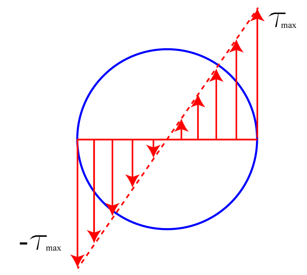
We have learned that maximal stress value is determined by
(3) 
where  is the polar moment of inertia and
  is the maximal distance of the cross-section points from the center. For the circular cross-section, we have
(4) 
We have  , and by using this value, we have
(5) 
By substituting (5) in (3), we obtain
(6) 
Next, we substitute (6) in (2), we obtain
(7) 
From the last equation, we have
(8) 
By substituting the values for the Torque, factor of safety, and shear yield stress in the last equation, we can easily calculate the shaft diameter .