 by
by This is my first post in a series of posts on how to use Raspberry Pi microcontrollers in complex mechatronics and machine learning projects. In this post, I will explain how to set up a Raspberry Pi microcontroller such that it can be easily used to send control signals to mechatronics components and to read sensor data. Furthermore, I will demonstrate how to implement a simple LED blink code. Here is a video about the post (continue to read for a detailed description).
Unlike Arduino microcontrollers, Raspberry Pi microcontrollers come without a framework for easy access to input-output pins. To establish such a framework, we will need a cobbler, ribbon cable, and a breadboard. Furthermore, we will need to install a WiringPi library which will enable us to control the Raspberry PI pins and read the data using the C code.
We need the following parts:
- Raspberry Pi 3 microcontroller
- Cobbler
- Ribbon cable
- Breadboard
- 560 [Ohm] resistor
- Light-emitting diode (LED)
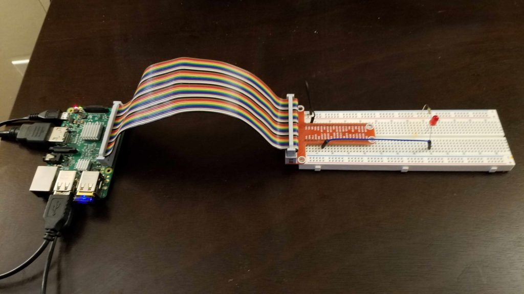
The sketch of the circuit is shown in Fig. 1 and a photograph is shown in Fig. 2.

Step 1- Install the WiringPi library
WiringPi library is a GPIO (General Purpose Input Output) library for Raspberry Pi. It enables us to control different types of mechatronics devices and obtain sensor measurements. The library can be downloaded here. Follow the instructions provided on the WiringPi website and install the library.
Step 2- Connect the components
Connect the components according to the sketch in Figures 1 above. The WiringPi library has its own system for denoting the Raspberry Pi pins. The explanation of this can be found here. The control voltage signals are sent through pin 11 (GPI017 pin on the cobbler). This is actually WiringPi pin 0. The circuit is grounded to pin 6.
Step 3- Write and compile the C code
The following code causes the LED to blink with the period of 0.5 [s].
1. #include <wiringPi.h>
2. int main(void)
3. {
4.     wiringPiSetup();
5.     pinMode(0, OUTPUT); // this corresponds to pin 11 (GPIO17)
6.     while(1)
7.       {
8.        digitalWrite(0,HIGH); delay(500);
9.        digitalWrite(0,LOW);  delay(500);
10.       }
11.  return 0;
12. }
A few comments are in order. On line 5, we declare that the pin 11 is the output pin. This pin is pin 0 in the WiringPi notation. On lines 8 and 9, we turn the LED on and off.
Open the Save this code in the file called “test1.c”. Open Terminal, and navigate to the folder in which this file is saved. The code is compiled by the following command:
g++ test1.c -l wiringPi -o blink
Here is the explanation.
– “g++” is the GNU C++ Compiler
– “test.c” is the name of the source file
– “-l wiringPi” is used to link the library, more details can be found here.
– “-o blink” is the name of the output executable file
The code is executed in Terminal by entering:
./blink
The execution of the code can be stopped by entering “ctrl-c”.