 by
by In this post, we explain two methods for generating Pulse Width Modulation (PWM) signals and for controlling servo motors using a Raspberry Pi microcontroller and a C code. The video of this project is given below, and a detailed explanation is given in the sequel.
So what is a servo motor? According to Wikipedia: ” A servomotor is a closed-loop servomechanism that uses position feedback to control its motion and final position “. These motor types are widely used in robotics and mechatronics applications. So, how do we control servo motors? Well, we control servomotors using PWM signals. Figure 1 shows a typical PWM signal. This signal is defined by the period T and by the pulse width t.

The rotation angle of a servo motor is controlled by changing the pulse width t. Figure 2 illustrates this principle. The rotation angle of the servomotor arm is proportional to the pulse width.
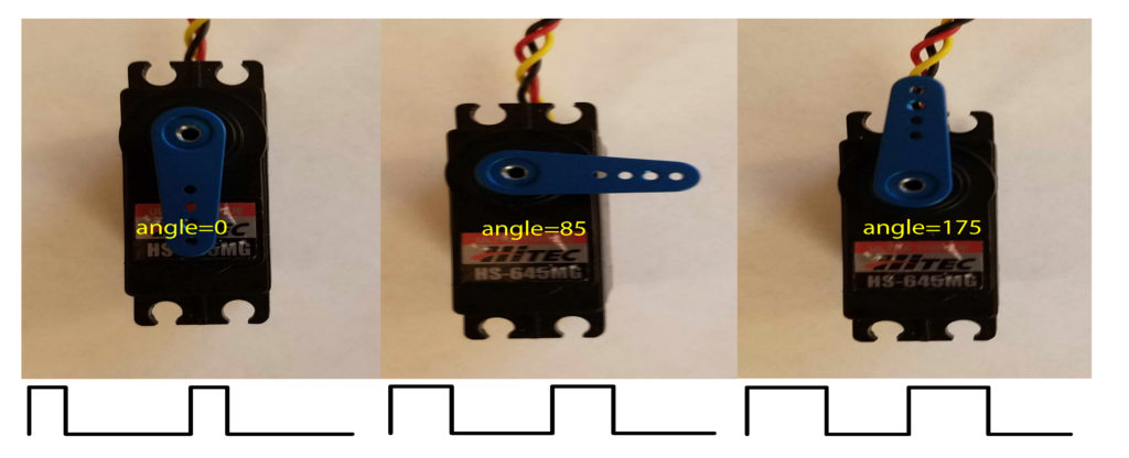
To demonstrate the basic principle of controlling servo motors, I am using a Hitec HS-645MG motor. Its photographs are shown in Fig. 2. This is a relatively pricey high-torque motor and its specifications can be found here and here.
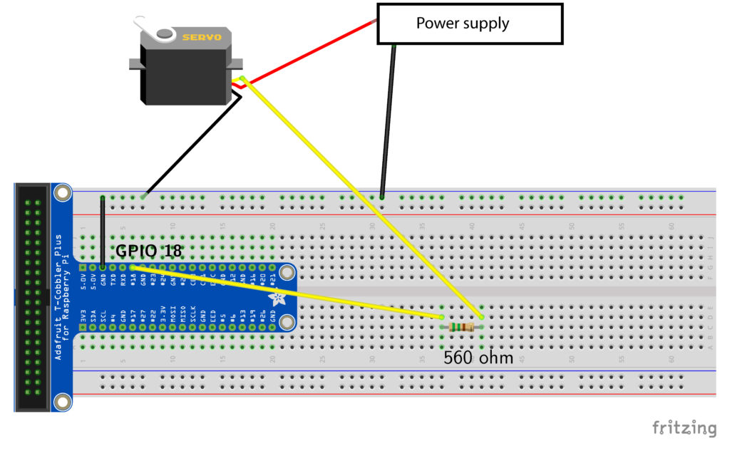
The wiring sketch is shown in Fig. 3. Basically, a servomotor has 3 wires. The yellow wire is a signal wire, whereas red and black wires are power and ground, respectively. The yellow wire is connected to the General Purpose Input Output (GPIO) pin 18. We will explain later why it is important to attach the signal wire to this pin. There are two methods for controlling the servomotor.
Method 1: Hardware PWM
Basically, GPIO pin 18 can be used to send hardware generated PWM signals. Typically, the PWM period for the servomotors is 0.02 [s] which corresponds to 50 [Hz] PWM frequency. However, most of servomotors can handle smaller PWM periods or equivalently, higher PWM frequencies. For brevity, we will set the PWM period to 0.02 [s]. The next step is to investigate the allowable ranges of the pulse length t. From the specifications given here, we see that the pulse width is in the range 553-2520 [μs] (μ is the microsecond unit). Furthermore, from the specifications given here , we see that the neutral servomotor position corresponds to 1500
[μs], and that 45 degrees rotation corresponds to 400 [μs] pulse.
#include<wiringPi.h>

int main(void)
{
	wiringPiSetupGpio();
	pinMode(18,PWM_OUTPUT);
	pwmSetMode(PWM_MODE_MS);
	pwmSetRange(2000);
	pwmSetClock(192);

	while(1)
	{
	pwmWrite(18,150);
	}
	return 0;
}
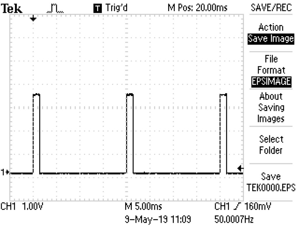
A few comments are in order. Line 5 is used to set up the system such that it uses the Broadcom GPIO pin numbers directly with no re-mapping. This function needs to be called with rood privileges. This numbering system directly corresponds to the numbering system shown on the cobbler. On line 6, we declare the pin 18 to be the PWM output pin. Line 7 sets the PWM generator to run in the “mark:space” mode, for more details, see the WiringPi webpage. Line 8 sets the range of the PWM register and line 9 sets the divisor for the PWM clock. The arguments of 2000 and 192 ensure that the period of the PWM signal is 0.02 [s]. That is, the PWM frequency is 50 [Hz]. How did we calculate these values? Basically, according to this post, the formula is: pwmFrequency [Hz] = 19.2e6 Hz / pwmClock / pwmRange.
In our case, we have: pwmFrequency [Hz] = 19.2e6 Hz / 192 / 2000=50 [Hz]. We verify this using an oscilloscope (see the video). The verification results are shown in Fig. 4.
On line 13, we set the pulse width t of the PWM signal. 150 corresponds to 1500 [μs]. How do we know this? We have that 19.2e6 Hz / pwmClock = 19.2e6 Hz / 192 = 10^5 [Hz]. This corresponds to 10 [μs] and this is the resolution of the PWM signal. Now, since the range is 2000, it follows that we have 2000 steps within one signal period. This corresponds to the total period of 0.02 [s]. So the value X in the function pwmWrite(18, X) is the pulse width t expressed in 10 [μs]. The value of 150 moves the servo motor arm to the neutral position (see the video).
How do we compile the code? Let us assume that the code is saved in the file “sudo_test.c”. The code is compiled and executed by typing
sudo g++ servo_test.c -l wiringPi -o servo_control
sudo ./servo_control
It is important to compile and run the code using the “sudo” command because otherwise Raspberry Pi crashes. The “sudo” command ensures that the code is run with the superuser privileges.
Method 2: Software PWM
Another for controlling servomotors is to use software generated PWM signals. A detailed explanation of this method is given here. The wiring of the circuit, shown in Fig. 3 is not changed. The code for controlling the servo motor is shown below.
#include<wiringPi.h>
#include<softPwm.h>

int main(void)
{
	wiringPiSetup();
	softPwmCreate(1,0,200);
	while(1)
	{
	softPwmWrite(1,15);
	}
	return 0;
}
Line 6 states that we are using the WiringPi notation for denoting the pins. Line 7 creates a software PWM pin. The first argument declares GPIO 18 to be a PWM pin (pin number 1 in the WiringPi notation). The second argument is the initial value, and the third argument determines the period of the PWM signal. The third argument multiplied by 100 [μs] determines the PWM period. This is the range. In our case it is 0.02[s] or 50 [Hz]. Finally, line 10, sends the PWM signal to the pin 1 (GPIO 18). The second argument of the function is the pulse duration t. The total duration of the pulse is the second argument times 100 [μs]. In our case, we are sending PWM signals with a pulse length of 0.0015 [s]. This signal steers the servo motor arm to its neutral position.
We assume that the code is saved in the file “servo_test_software.c “. The code is compiled by typing:
g++ servo_test_software.c -l wiringPi -l pthread -o servo_control_software
Notice that we had to link an additional library (pthread library). The code is executed by typing:
./servo_control_software
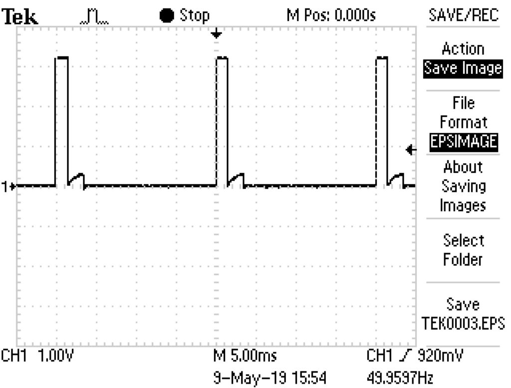
Figure 5 shows the oscilloscope measurement of the PWM signal. Notice that the signal is not as clean as in the case of the hardware PWM. As a consequence, the servo motor arm jitters around its neutral position.
Conclusion
It is more preferable to work with the hardware PWM than with software based PWM control for servo motors.
References
https://www.pololu.com/blog/17/servo-control-interface-in-detail
http://www.basicx.com/Products/robotbook/servo%20intro.pdf
https://www.pc-control.co.uk/servo_control.htm
http://www.hertaville.com/rpipwm.html
https://learn.adafruit.com/adafruits-raspberry-pi-lesson-8-using-a-servo-motor/software
https://raspberrypi.stackexchange.com/questions/4906/control-hardware-pwm-frequency
https://www.instructables.com/id/RaspberryPi-Pulse-Width-Modulation-Demonstration/