 by
by Raspberry Pi (RP) is a great device for rapid prototyping of mechatronics systems. In our previous post, we explained how to use this device to send control signals to servo motors. On the other hand, in many mechatronics applications, we need to read data from various sensor types, such as distance, temperature, and pressure sensors. These data are often given in the form of analog voltage signals. In order to process this data using RP microcontrollers, the analog signals need to be converted into digital signals. Electronic devices used to convert analog to digital signals are referred to as Analog-to-Digital (AD) converters. However, RP devices are not produced with AD converters. Consequently, additional circuitry and devices need to be coupled with RP devices in order to read analog signals.
In this post, we explain how to attach and use an external AD converter with RP devices and how to read data from a temperature sensor. A video accompanying this post is posted on YouTube and is given below.
For AD conversion we use an MPC3008 chip. This is a low-cost AD converter. It has 8 channels and can read up to 200 ksps (kilo samples per second). The resolution of this device is 10 bit, meaning that it can detect voltage increments of V_{ref}/(2^{10})= V_{ref}/(1024), where V_{ref} is the reference voltage. Typically, V_{ref}=3,3 or V_{ref}=5 [V].
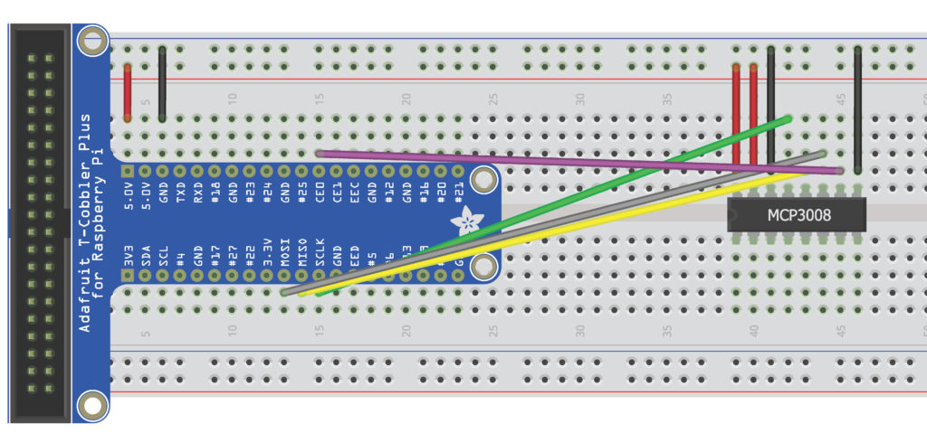
The wiring diagrams of the MCP3008 chip are shown in Fig.1 and Fig. 2.
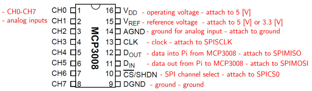
The analog inputs should be attached to channels CH0-CH7. The data read from any of the channels is in the integer interval 0-1023. This raw data is converted to voltage using the following formula:
voltage=(Vr * data) /1024
where data is the raw data obtained by the AD converter. In our case Vr=5 [V].
We demonstrate the usage of the AD converter on a temperature measurement experiment. We use a low-cost temperature sensor. More specifically, we use a TMP36GZ temperature sensor. Its main specifications can be found here. This sensor has a linear temperature-voltage calibration curve. A simplified wiring diagram of the temperature sensor is shown in Fig. 3.
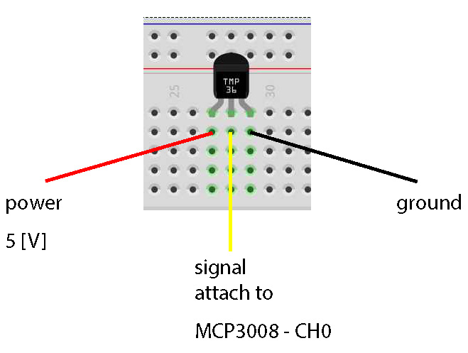
Sensor specifications suggest adding a 0.1 [micro F] bypass capacitor between the power and ground. The voltage read from the sensor using the AD converter is transformed to temperature readings using the following formula:
temperature=(voltage-0.5)*100
where 0.5 is the offset value and 100 is the proportionality constant of the temperature-voltage calibration curve.
We use a WiringPi library (see our previous posts) to read the data. The code is given below.
#include <wiringPi.h>
#include <mcp3004.h>
#include <iostream>
using namespace std;


int main(void)
{
	float raw_data=0;
	float voltage=0;
	float temperature=0;
	wiringPiSetup();
	mcp3004Setup(100,0);

	while(1)
	{
		raw_data=analogRead(100);
		voltage=(raw_data*5)/1024;
		temperature=(voltage-0.5)*100;
		cout<<"Raw data: "<<raw_data;
		cout<<" Voltage: "<<voltage;
		cout<<" Temperature: "<<temperature<<endl;
		delay(250);

	}
  return 0;
}
A few comments are in order. The lines 12-13 are used to set up the pins. On line 17 we read the analog data, and the lines 18-19 are used to convert the measurements into temperatures using the previously explained procedure. More details about AD conversion and temperature sensing can be found in the accompanying video.
Here are a few useful links on MCP3008 and temperature sensor TMP36GZ.
MCP3008 links:
http://shaunsbennett.com/piblog/?p=266
https://learn.adafruit.com/raspberry-pi-analog-to-digital-converters/mcp3008
Temperature sensor link:
https://learn.adafruit.com/tmp36-temperature-sensor/overview