 by
by
In this strength of materials and mechanics lecture, we will analyze the stress field under the influence of an axial force. We will be interested in a stress field on an oblique plane. The oblique plane is an internal imaginary cut plane that forms a certain angle with respect to the direction of the axial force acting on the body. The synonyms of the word oblique are inclined and angled. That is, instead of saying “an oblique plane”, we can also say “inclined plane” or “angled plane”. In this tutorial, we will show that on the oblique plane, there are both shear (tangential) and normal stresses. That is, on the oblique plane we will have at the same time shear and normal stress components. Also, we will show that the shear stress is maximum for the oblique plane forming 45 degrees with the direction of the force. The YouTube tutorial accompanying this post is given below.
Static Force and Stress Analysis on Oblique Plane
When we introduced normal and shear stresses, we used a vertical cut plane. We have discovered that if forces are axial (tensile or compressive), then we only have normal stresses caused by the internal resultant force that is perpendicular to the cut plane.
Here we will try to answer the following question:
What happens when the imaginary cut plane is inclined with respect to the direction of the acting force, that is, what is a stress distribution when we have an oblique cut plane?
Consider the situation sketched in Fig. 1.


The upper part of Fig. 1, shows an element that is axially loaded by the two forces  . Consider a segment shown in the lower part of the figure. This segment is defined by cutting the element by an oblique plane. Similarly to the previous cases of normal and shear stresses, we have an internal force resultant , and in order for the segment to be in equilibrium, the intensity of this force has to be equal to the intensity of force , that is
(1) 
Now, our task is to define normal and shear stresses induced by the force . To define these stresses, we have to recall the stress definitions. Normal stress is defined as a normal force divided by the surface area. On the other hand, shear stress is defined as a shear force (the force that belongs to the cutting plane) divided by the cross-section area. Consequently, we have to resolve, or better to say to project the force into two components. The first component will be projected onto the direction normal to the cutting plane, and the second component will be projected onto the direction tangent to the cutting plane (the component that belongs to the oblique plane). This is illustrated in Fig. 2 below.
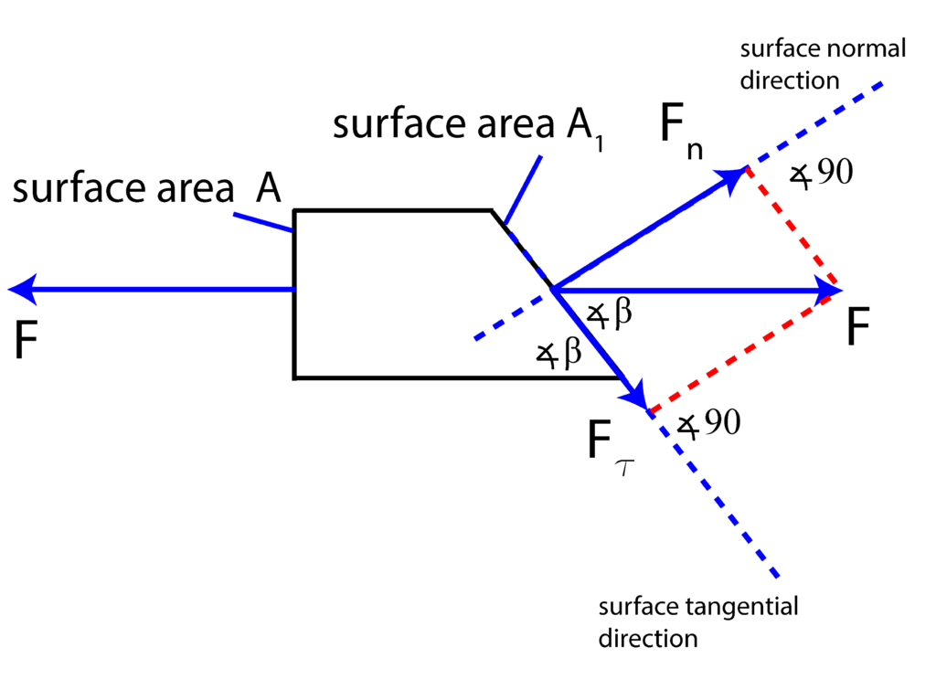
We have two projections defined by
(2) 
On the other hand, from basic geometry, it follows that the area of the oblique surface is defined by
(3) 
Consequently, we define the normal and shear stresses as follows
(4) 
(5) 
With this derivation, we have demonstrated that in the oblique plane, defined by the angle  , we have at the same time normal and shear stresses.
What is interesting to show is that shear stresses are maximal for the angle of  degrees. This can be shown by observing that
(6) 
where we have used the well-known fact that  . Since the sinus function
  reaches the first maximum for
  , and in our case
  , we conclude that for
  degrees, the shear stress
  reaches the maximum.