 by
by In this post, we explain the purpose and basic usage of pull-up and pull-down resistors and we explain the purpose of interrupts in Raspberry Pi microcontrollers. A detailed video accompanying this video is given below.
Pull-up/pull-down resistors are resistors used to ensure that a signal has a defined state, that can be low (logical 0) or high (logical 1). On the other hand, loosely speaking interrupts are external events (signals) that tell the microcontroller (or better to say its CPU) to execute a certain piece of code immediately after the end of the current instruction. For example, you want to make sure that the microcontroller responds and performs an action once a button has been switched.
First, we explain pull-up resistors. Consider the following diagram shown in Figure 1.
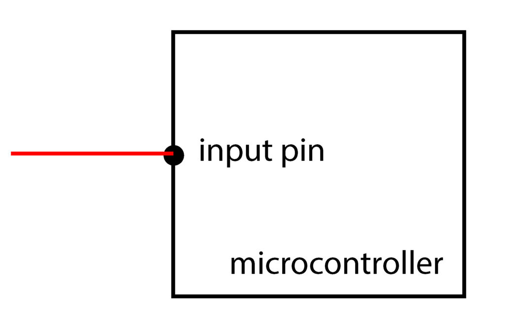
Let us suppose that the input pin shown in the figure is defined as a digital input pin. Also, let us suppose that nothing is connected to the input pin. After reading the state from the pin, we want to see is the state high or low? That is, what is the value of the voltage at the pin (digital high or digital low)? The state is uncertain and this is a situation that we would like to avoid. The above-explained problem is often referred to as the floating phenomenon. To resolve this we can use pull-up or pull-down resistors. Figure 2 below shows the basic usage of a pull-up resistor.
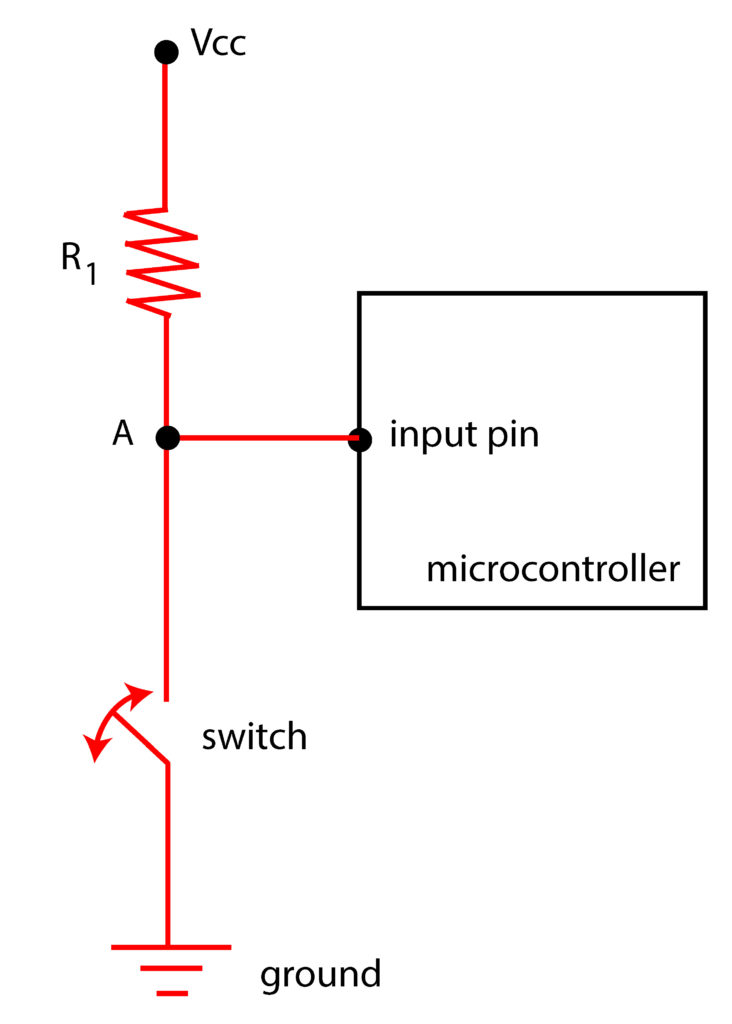
The resistance  should be selected such that it is at least an order of magnitude smaller than the internal impedance (resistance) of the input pin. For example, if the input impedance is in the order of
 ![100- 1000 [k\Omega ]](https://aleksandarhaber.com/wp-content/ql-cache/quicklatex.com-54d4290536ac4129965be06de8b4760d_l3.png "Rendered by QuickLaTeX.com") , then the pull-up resistance should be for example
, then the pull-up resistance should be for example ![4.7 [k\Omega]](https://aleksandarhaber.com/wp-content/ql-cache/quicklatex.com-3319c9560c927c166789e5832bd658a2_l3.png "Rendered by QuickLaTeX.com") or
or ![10 [k\Omega]](https://aleksandarhaber.com/wp-content/ql-cache/quicklatex.com-59d31e91bfb6d2a59e2266a8c892897a_l3.png "Rendered by QuickLaTeX.com") . Under this condition and when the switch is open (for example when an external button is not pressed), the voltage of node A in Fig. 2 will be approximately equal to Vcc (coming from the power source). Consequently, the state of the input pin will be high when the switch is open (that is, the state will be equal to the logical 1). This is why the resistor is called the pull-up resistor. It pulls the state to the high value when the switch is open. When the switch is closed (the button is pressed), the voltage at the point A (the potential) is grounded. That is the state of the input pin is low, corresponding to the logical 0. In this way, we can prevent the floating phenomenon, and always have a definite value of the state at the input pin. Figure 3 below gives more details on understanding the internal input impedance of the microcontroller pin. The internal input impedance is represented by a dashed line with the resistance of
. Under this condition and when the switch is open (for example when an external button is not pressed), the voltage of node A in Fig. 2 will be approximately equal to Vcc (coming from the power source). Consequently, the state of the input pin will be high when the switch is open (that is, the state will be equal to the logical 1). This is why the resistor is called the pull-up resistor. It pulls the state to the high value when the switch is open. When the switch is closed (the button is pressed), the voltage at the point A (the potential) is grounded. That is the state of the input pin is low, corresponding to the logical 0. In this way, we can prevent the floating phenomenon, and always have a definite value of the state at the input pin. Figure 3 below gives more details on understanding the internal input impedance of the microcontroller pin. The internal input impedance is represented by a dashed line with the resistance of 
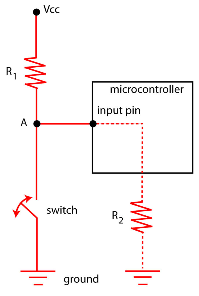
Using the voltage divider formula and under some mild approximations, we can see that the voltage at the point A when the switch is open is given by
(1) 
where
is the internal resistance of the input pin. When ![R_{2}=1000 [k\Omega]](https://aleksandarhaber.com/wp-content/ql-cache/quicklatex.com-27fa40ce4ea37f9bfb98d3ed57be7534_l3.png "Rendered by QuickLaTeX.com") and
and ![R_{1}=10 [k\Omega]](https://aleksandarhaber.com/wp-content/ql-cache/quicklatex.com-99cff72a1d52128e45160a23d4d178b4_l3.png "Rendered by QuickLaTeX.com") , we have
, we have  when the switch is open. Let us now briefly discuss the pull-down resistors. Figure 4 shows an application of pull-down resistors.
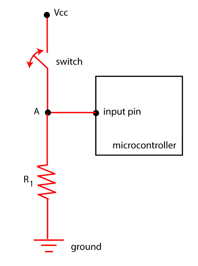
From Fig. 4 we can see that when the switch is open, the resistor “pulls down” the state of the input pin to the low value. On the other hand, when the switch is closed, the input pin state is high since the input pin is directly wired to the Vcc voltage. Most of the microcontrollers including Raspberry Pi and Arduino have internal pull-up or pull-down resistors. However, in this post, for the sake of learning, we will not use internal resistors.
Next, we explain interrupts. We will use Raspberry Pi to explain the interrupts, and a similar principle can be used in the case of an Arduino microcontroller. Figure 5 shows a switch attached to the pull-up resistor.
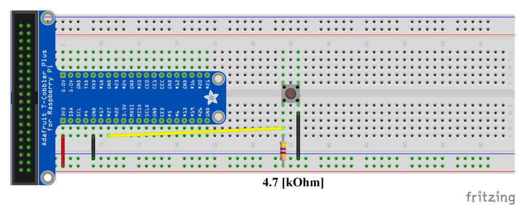
For more details on how to set up Raspberry Pi for this project, see our previous post. A cobbler is used to interface the Raspberry Pi with the breadboard. We use a pull-up resistor. When the button is not pressed, the voltage value that is read at the GPIO 27 is high, that is it is approximately equal to ![3.3 [V]](https://aleksandarhaber.com/wp-content/ql-cache/quicklatex.com-5e07a6160d81a83625f6362f26aa97ff_l3.png "Rendered by QuickLaTeX.com") (this is the supply voltage coming from the Raspberry Pi). That is, the state corresponds to the logical
(this is the supply voltage coming from the Raspberry Pi). That is, the state corresponds to the logical  . When the button is pressed, the GPIO 27 pin is grounded, that is the state corresponds to the logical
  . The following code illustrates the basic usage of interrupts.
#include <wiringPi.h>
#include <iostream>

using namespace std;

unsigned int noPressed=0;
int inputA=2; // BCM 27 or GPIO-27


void functionA()
{
	noPressed++;

}


int main()
{

wiringPiSetup();
wiringPiISR(inputA,INT_EDGE_FALLING,&functionA);
// here my WordPress plugin misinterprets the symbol the ampersand symbol, it adds "amp;" so correct this in your code, otherwise the code will not execute!

while (1)
{
	 cout<<"Button is pressed "<< noPressed<< " times "<< endl;
}

}
This code counts the number of times the button has been pressed. Notice that nowhere in the main function we are actually doing a digital read of the GPIO27. We are just printing the message that counts the number of times the button has been pressed. If the button is pressed, then the interrupt is activated and the function “functionA()” in the code lines 10-14 is executed. This function increases the counter “noPressed” that counts how many times the button has been pressed. This is possible since on the code line 21 we have defined an interrupt. We are saying that the interrupt should be attached to the “inputA” (that is, the GPIO 27), and that we are going to detect the falling signal. That is, we are measuring the number of times the signal drops from a high value to the low value. The last argument of this function is the specification of the function that will handle the interrupts. In our case it is “functionA()”.
Now, we have to mention that this code is susceptible and sensitive to another important problem. This problem is often referred to as the debouncing problem. Namely, it may happen that immediately after the button is switched, the signal bounces off and debounces back to the low value. In this case, our code will artificially detect two events, and it will count one even two times. To prevent this, it is important to use debouncing techniques that will be explained in our next post.
Here are some references for further study of pull-up/pull-down resistors and interrupts:
https://www.elprocus.com/pull-up-and-pull-down-resistors-with-applications/
http://www.resistorguide.com/pull-up-resistor_pull-down-resistor/