In this lecture, we introduce the concept of shear stress.
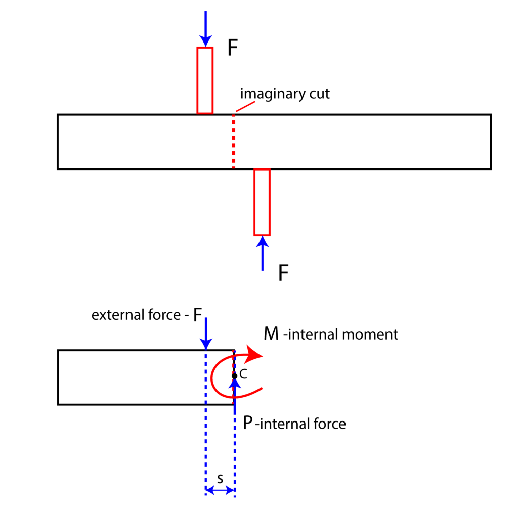
Consider the load scenario and a 2D sketch of an element shown in Fig. 1 below.

We have two elements that exert the force ![]() onto the horizontal element. Let us assume that the horizontal element is in static equilibriium. Consider the imaginary cut shown in the upper subfigure of Fig. 1. The lower subfigure shows what happens at the imaginary cut plane. In order for the system to be in static equilibrium, we need to add an internal force
onto the horizontal element. Let us assume that the horizontal element is in static equilibriium. Consider the imaginary cut shown in the upper subfigure of Fig. 1. The lower subfigure shows what happens at the imaginary cut plane. In order for the system to be in static equilibrium, we need to add an internal force ![]() and an internal moment (of a couple), denoted by
and an internal moment (of a couple), denoted by ![]() . From the static equilibrium conditions, we obtain
. From the static equilibrium conditions, we obtain
(1) 
and from the moment equilibrium equation we obtain
(2) 
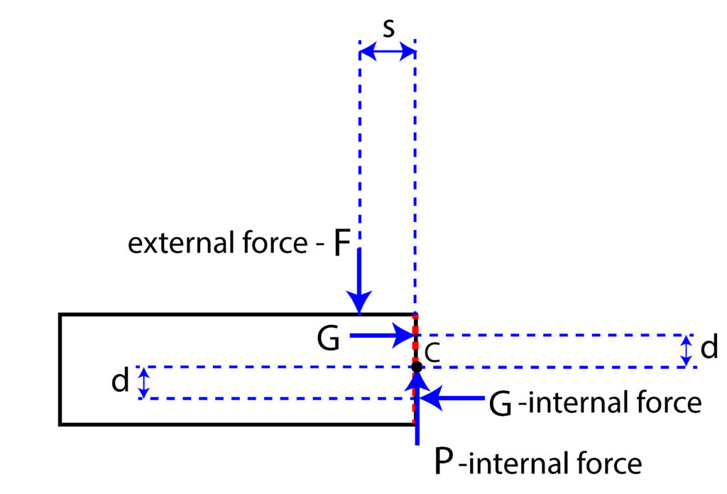
However, moment ![]() is just a consequence of the applied forces. That is, this moment needs to be represented by forces. One possibility is shown in Fig. 3 below.
is just a consequence of the applied forces. That is, this moment needs to be represented by forces. One possibility is shown in Fig. 3 below.

 is represented by a system of forces
Here it should be kept in mind that similarly to the tensile forces, the force ![]() is the resultant of the internal forces. From Fig.3, we see that the moment equilibrium equation has the following form
is the resultant of the internal forces. From Fig.3, we see that the moment equilibrium equation has the following form
(3) ![]()
By comparing (2) and (3), we can observe that ![]() , and that is exactly the moment of the couple formed by the two forces
, and that is exactly the moment of the couple formed by the two forces ![]() . From the last equation, we obtain that
. From the last equation, we obtain that
(4) ![]()
However, this is only one possiblity for the normal force distribution in the imaginary cut plane. There many other possiblities. This problem will be analyzed in more details during presentation of bending.
If ![]() is relatively small, then we can neglect the force
is relatively small, then we can neglect the force ![]() and the resulting moment. In that case, we only have the internal force
and the resulting moment. In that case, we only have the internal force ![]() “living” in the imaginary cutting plane.
“living” in the imaginary cutting plane.
We define the shearing stress as
(5) ![]()
where ![]() is the aread of the cross section of the element, and
is the aread of the cross section of the element, and ![]() (Greek letter) is a symbol for shearing stress.
(Greek letter) is a symbol for shearing stress.