 by
by
In this LTspice tutorial, we explain how to simulate a low-pass active filter in LTspice. The YouTube video is given below.
The filter structure is shown in the figure below. It consists of an operational amplifier, two resistors  and
and  and the capacitor
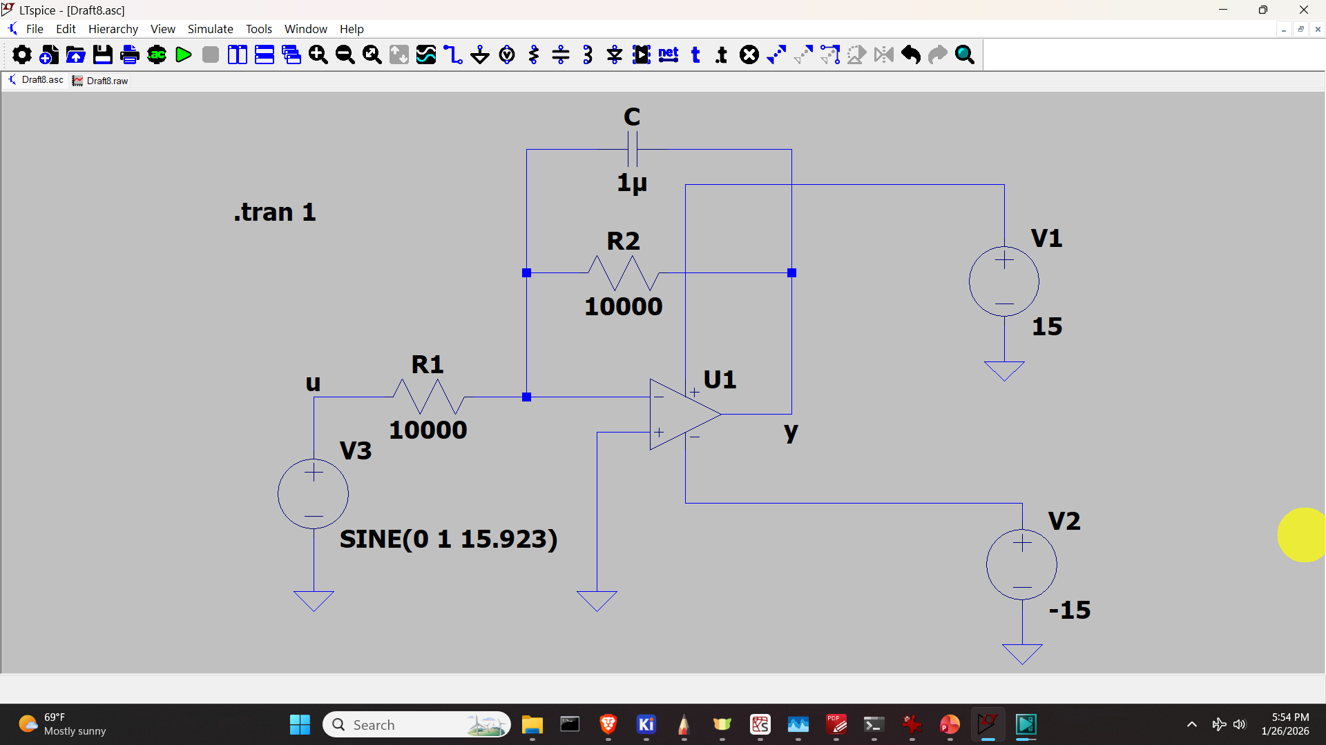
To validate the simulation results, we use a basic theory of low-pass filters. Namely, it can be shown that the break frequency of this filter is
(1) 
Under the assumption that  , the attenuation of the filter should be 0.707 when the input sinusoidal signal has the frequency equal to the break frequency. This formula can be used to validate the simulation results. Namely, if we select the input signal such that its frequency is equal to the break frequency, then the attenuation should be 0.707. This is exactly what are simulation results shown below are showing:

The figure below shows the basic formulas of the active low-pass filter
