 by
by
In this mechanics and strength of materials lecture, we explain how to draw shear force and bending moment diagrams by hand. In this lecture, we explain the procedure in the case of a single concentrated force (concentrated load) that acts at a single point of a simply supported beam. The YouTube video accompanying this post is given below.
Problem Formulation
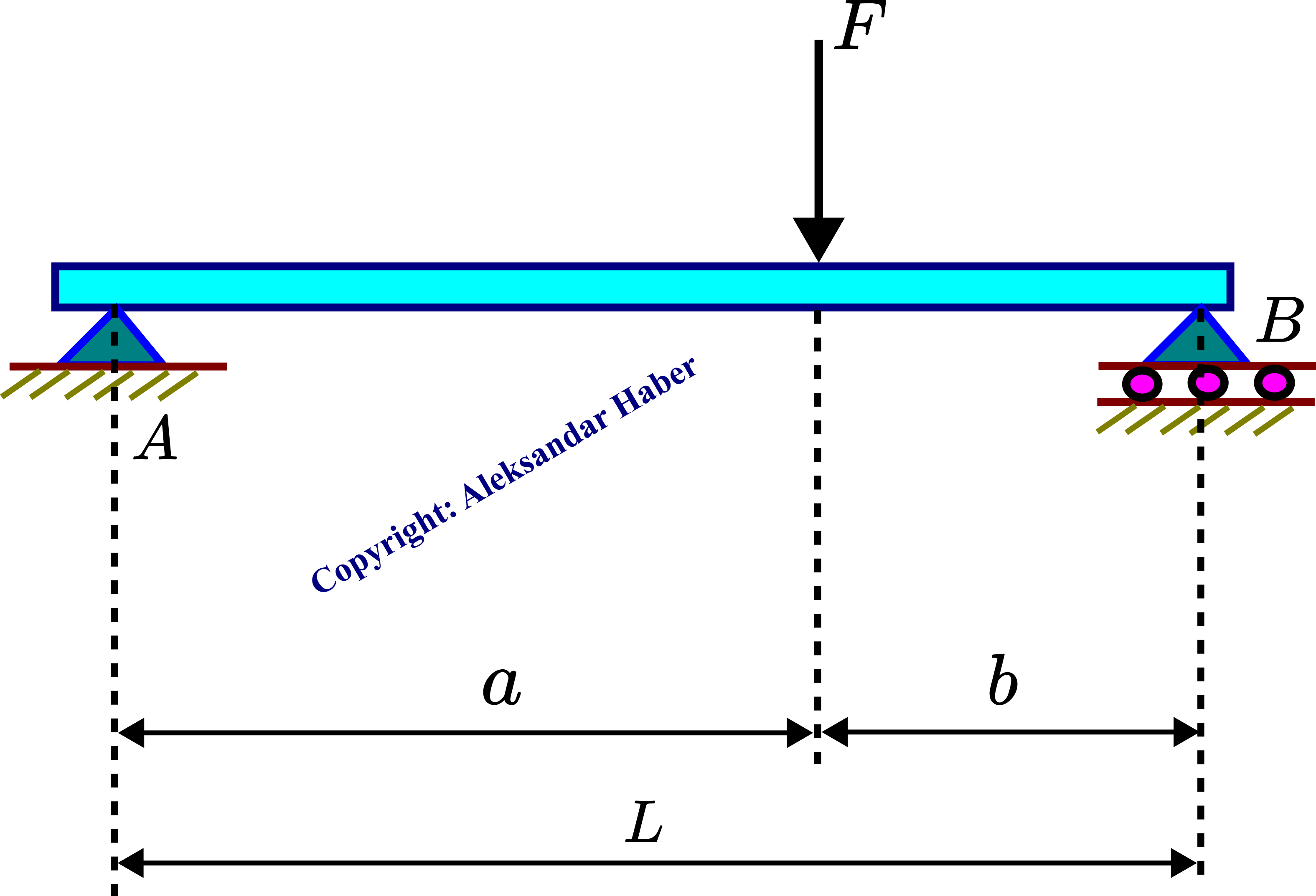
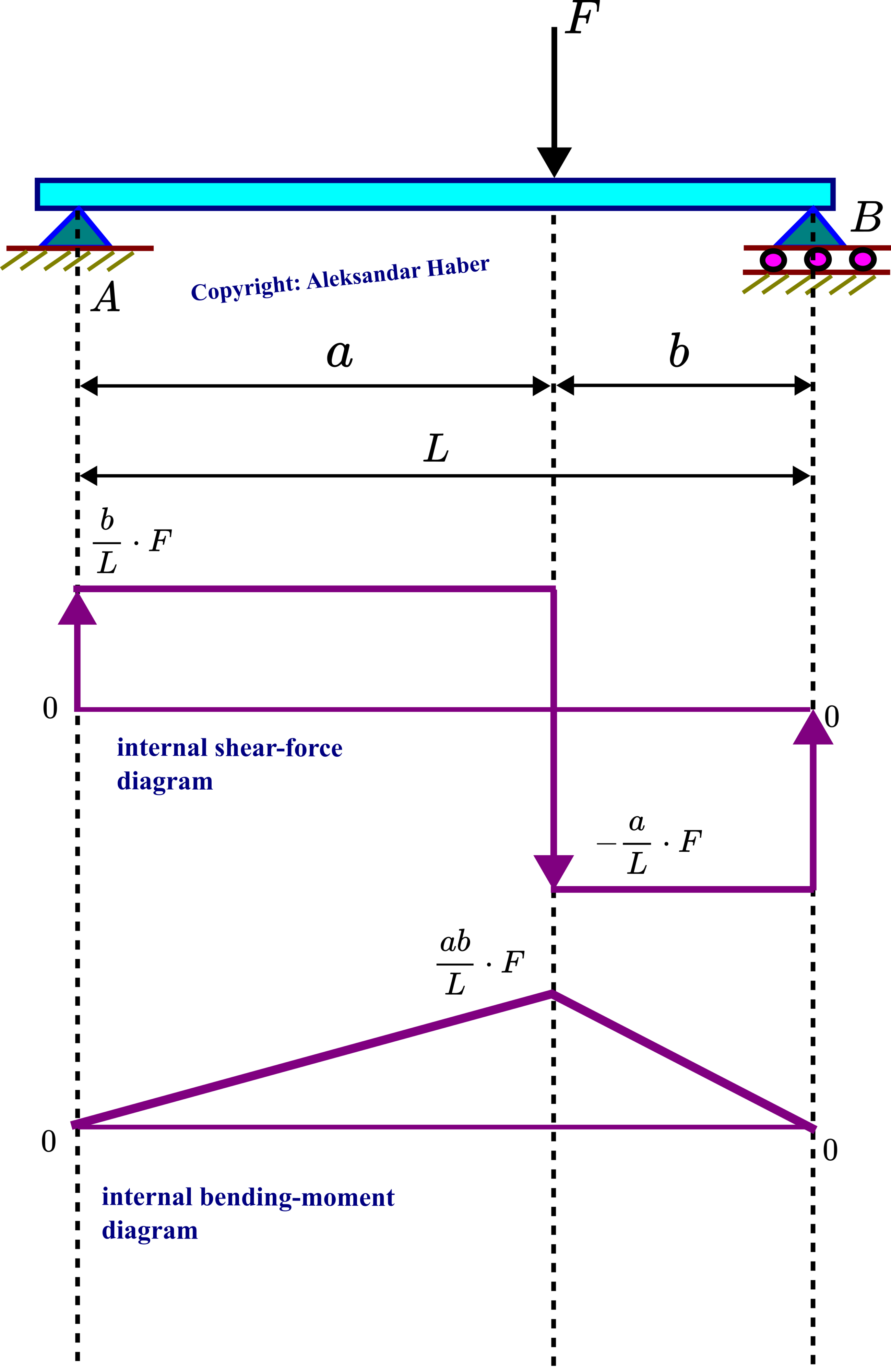
Consider a simply supported beam shown in the figure below. A concentrated force  is acting at distance
  from the point
  . Under the assumption that the distances and
  , and the length
  are known, draw shear-force and bending-moment diagrams of the beam.
Solution
The first step is to construct a free-body diagram. By removing the supports and  , and by replacing the action of supports by reaction forces, we obtain a free body diagram shown in the figure below.
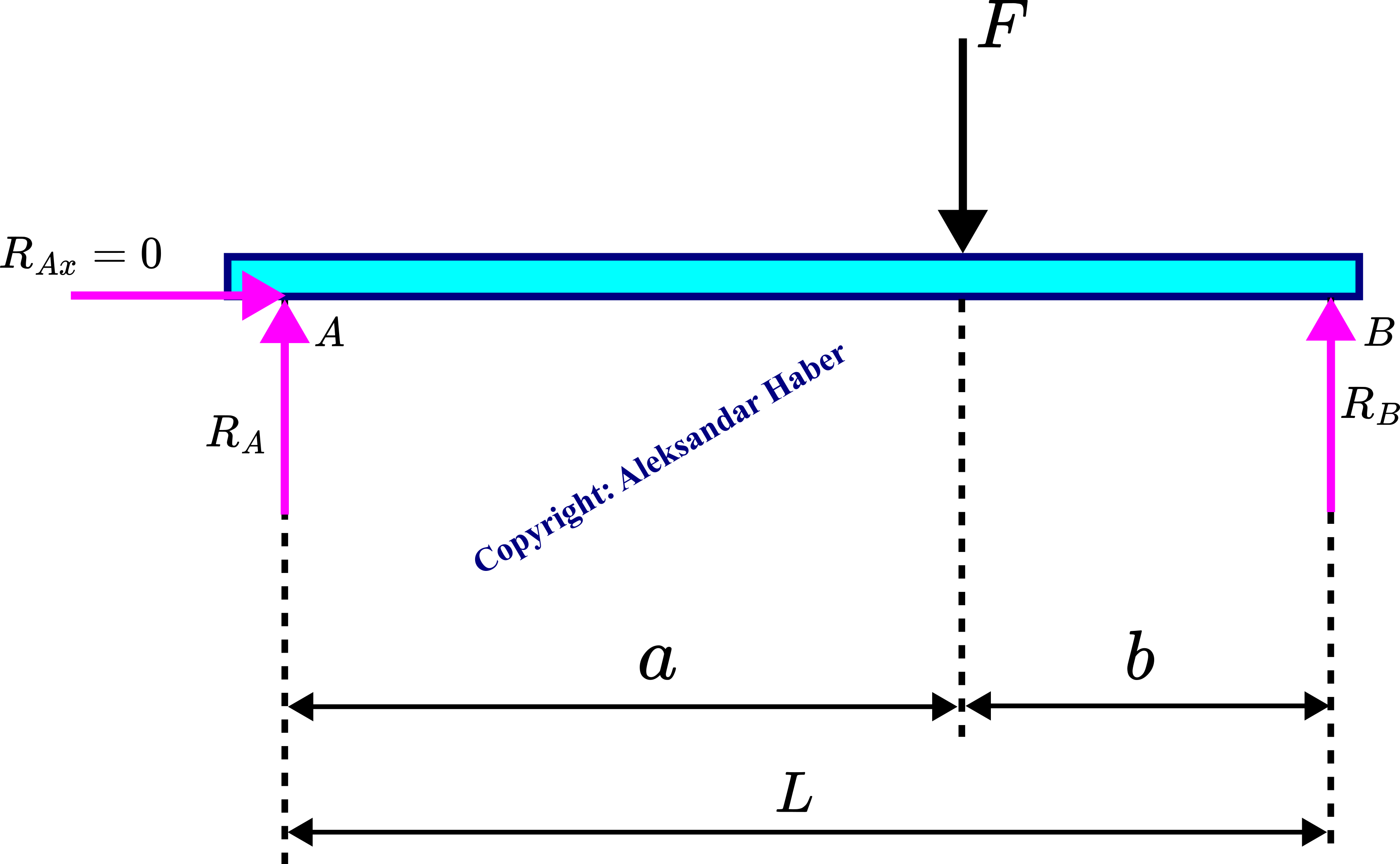
The reaction forces are  ,
,  and
and  . We need to determine these reaction forces in order to construct the shear-force and bending-moment diagrams. The sum of forces acting on the beam should be equal to zero:
(1) 
The horizontal reaction force at the support is equal to zero since the external force is only acting in the vertical direction. By projecting the force balance equation (1) onto the vertical axis, we obtain
(2) 
Next, we need to write a moment balance equation. The sum of all the moments around any point of all the forces acting on the beam should be equal to zero. Let us select the point , and let us write the moment equation for this point
(3) 
where the moment of the force is equal to zero since the action line of this force passes through the point . From (3), we can determine the reaction force
(4) 
On the other hand, by substituting (4) in the equation (2), we obtain
(5) 
Next, in order to construct diagrams, we need to introduce the sign convention for the internal shear forces and bending moments (bending couples). Consider the figure below.
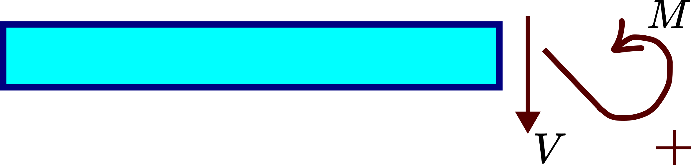
 and the internal-bending moment M in a cross-section.
 Fig. 3, shows a cross-section of a beam with the internal force and in the internal moment  . If the internal shear force and internal bending moment in the cross-section are oriented as in Fig. 3, they have a positive sign.
To construct shear-force and bending-moment diagram, we need to define the two cross-sections shown in the figure below.
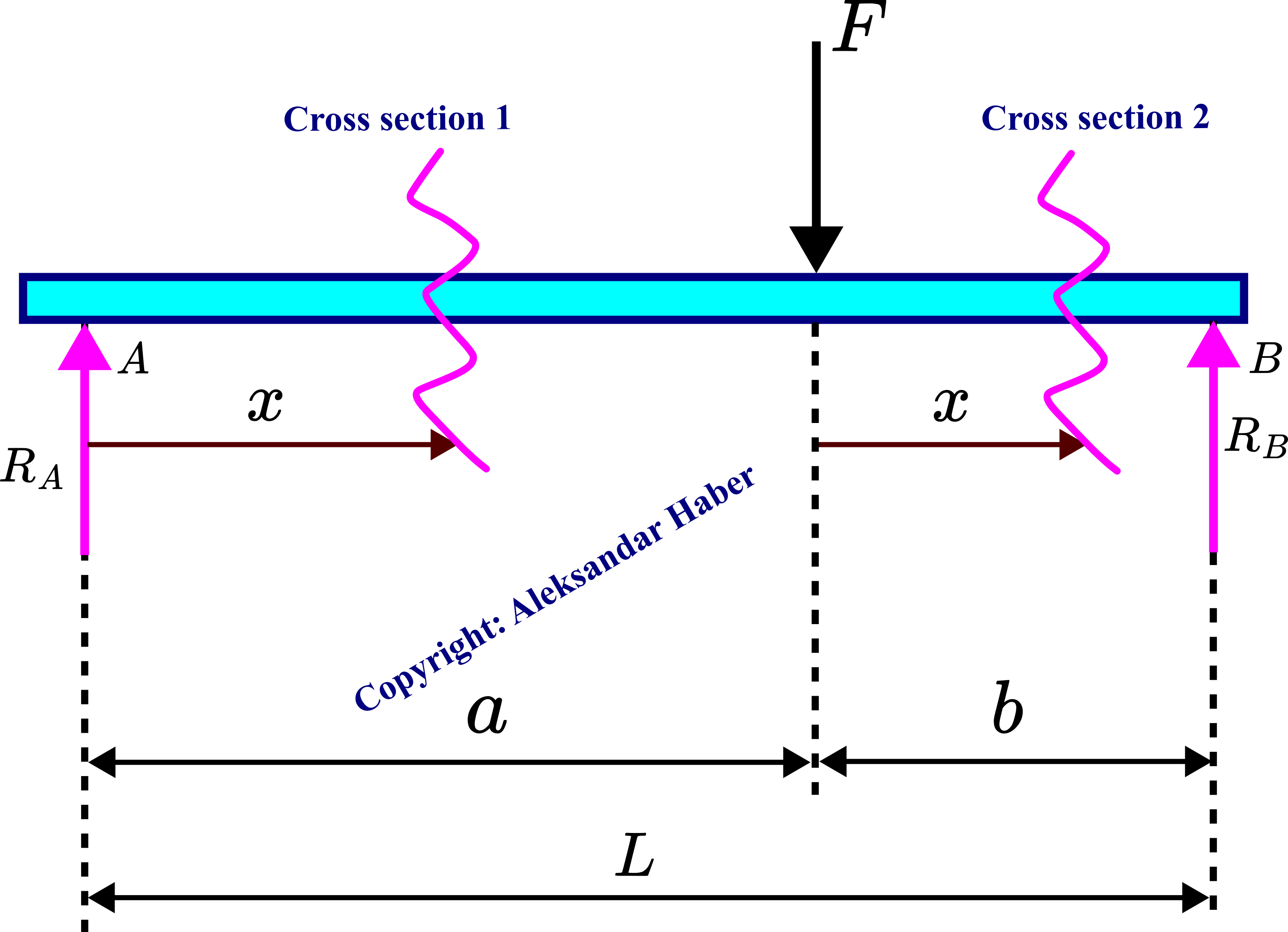
We start with the cross-section  . Consider the figure shown below. In this cross-section, the variable
  is in the interval from
  to .
to .
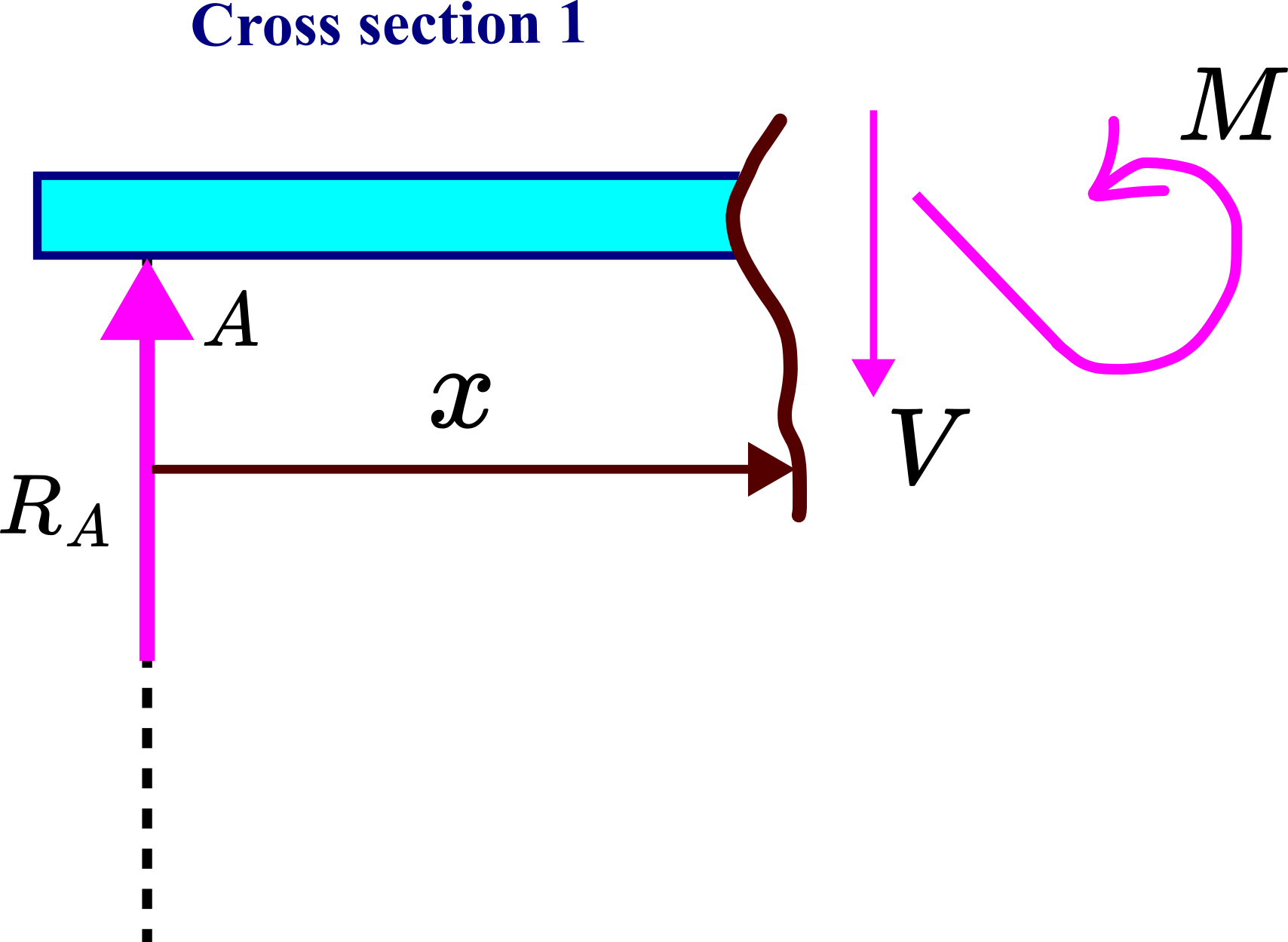 and internal bending moment .
We created an imaginary cut (cross-section) of the beam at the distance from the support . We erase everything on the right-hand side of the cross-section, and only take into account external forces and couples (moments) on the left-hand side of the cross-section. Since on the left side of the cross-section 1, we have the reaction force , for the system to be in the static equilibrium, we need to add an internal shear force and an internal bedding moment (also known as bending couple). From the static equilibrium force equation, we have
(6) 
From the static equilibrium moment equations written for the point , we have
(7) 
The cross-section 2 is shown in the figure below. In this cross-section, the variable is in the interval from to .
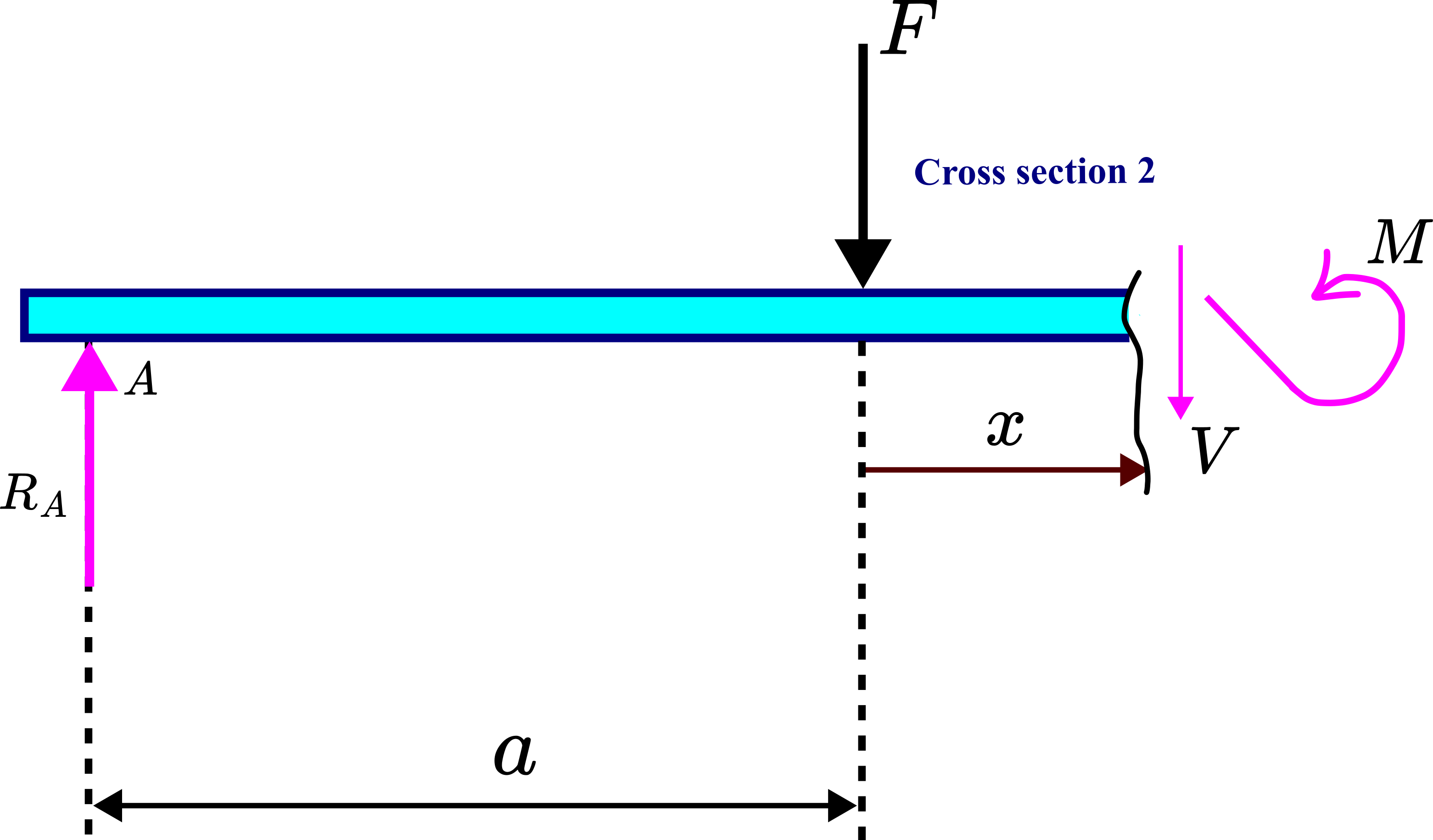 and internal bending moment .
The static equilibrium force equation is
(8) 
The static equilibrium moment equation for the point is
(9) 
The shear-force and bending-moment diagrams are given in the figure below.
A good verification of the correctness of the derived equation is to compare the internal moment equations (7) and (9). The equation (7) written for  should give the same value as the equation (9) written for
  . Let us perform this comparison. By substituting in (7), we obtain
(10) 
On the other hand, by substituting in (9), we obtain
(11) 
We can observe that these two equations produce the same value of the moment. Another test is that for in (7) and for  in (9), we should get zero values of the moment equation. We can easily verify that this is the case.
Another test is the following. The derivative of the moment equation with respect to should produce the value of the shear force. For the cross section 1, we take the derivative of (7):
(12) 
and that is precisely the value of given by (7). On the other hand, if we take the derivative of (9) with respect to , we obtain
(13) 
and that is precisely the value of given by (8).