Figure shown below illustrates a Pulse Width Modulation (PWM) signal.

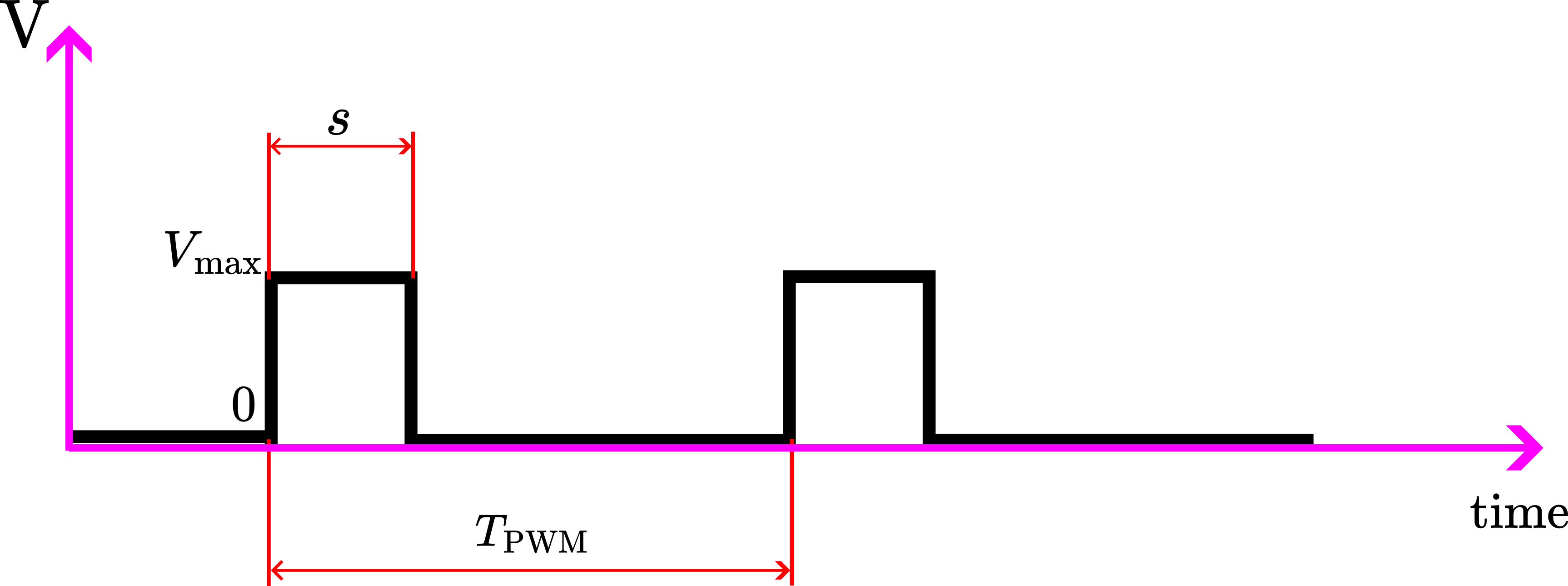
The PWM signal is defined by the following variables


The frequency of the PWM signal is
(1) 

The duty cycle is defined by
(2) 

In the STM32 development environment, we select the frequency of the PWM signal by using the three parameters 


(3) 

where
-
The frequency the time clock
In the STM32CubeIDE development environment:
- The period


In the STM32CubeIDE environment, the duty cycle is determined by
(4) 

where 


Let us illustrate this with an example. Let us suppose that we want to generate a PWM signal with the frequency of 


(5) 
